
A gyroscope is a device for measuring or maintaining orientation, based on the principles of angular momentum.
Almost every gyroscope chip has to be calibrated, because every device brings a manufacturing error.
In case of gyroscope the correction parameters we need are gain and offset.
Once you obtain those values you can get calibrated data by applying this formula:
x_calibrated = (x_raw-offsetx) / gainx
y_calibrated = (y_raw-offsety) / gainy
z_calibrated = (z_raw-offsetz) / gainz

This Python script implements a simple Gyroscope calibration routine to estimate offset and gain calibration values.
To calibrate offset we just leave gyroscope in a stable position.
To correct gain, this script do not use a calibrated rotation platform. I use an integration method. User must rotate it in 6 differenct way (see sheet provided) for a fixed angle, i use 90 degrees, cause i can do it with a simple calibration platiform (a cube), but greater angles (3600) would bring to better calibration.
The rotation plane of the gyroscope have to be parallel to the requested rotation, so try to be precise placing the sensor over a rotation platform, and rotating it.
During every rotation the script collect raw values. Integrating those values gives use the raw total values for the angle formed. Because we fixed the angle we should estimate the gain factor for the raw values. I sense the rotation stop evaluating raw values, a better way should be adding stop sensors. I suggest to repeat calibration more than one time, cause small rotation error can lead to calibration error.
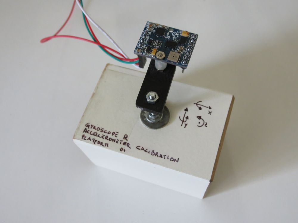
To obtain values, run this script and follow the instructions, a calibration sheet is provived to help you directing the sensor.
If you run your sensor in a big range of temperature you should also consider a calibration dependent to temperature too.
You can run the script function that compute temperature compensation values.
Cool down you chip, then launch the script, while the sensor come back to ambient temperature, this script collect values, then compute linear regression to find suitable temperature compensation values.
Now, given a tempdelta, that is a temperature delta difference from the sensor start time
tempdelta = actualtemp - starttimetemp
The calibrated axis would became:
x_calibrated = (x_raw-((tempcompx*tempdelta) + offsetx)) / gainx
y_calibrated = (y_raw-((tempcompy*tempdelta) + offsety)) / gainy
z_calibrated = (z_raw-((tempcompz*tempdelta) + offsetz)) / gainz
You may repeat those tests a few times to get better results.
On the microcontroller side you have to setup a function that print out to UART raw values read from your chip.
Given 2 bytes (int16_t) variables for every axis, output the LSB and then MSB byte ((uint8_t)(int16_t>>0) + (uint8_t)(int16_t>>8)), follow by a '\n' char .
Snippets are provided for AVR Atmega and Arduino, but it can be setup for other micro too.
Changelog
- 02: small fix on the gyro_docalibration.txt readme file for the tempcomp function for x_calibrated, y_calibrated, z_calibrated
- 01: first version
Code
Notes
- read risk disclaimer
- excuse my bad english
thank you!
ReplyDeletethank you for this calibration method
ReplyDeletecan you give me your reference for this method? because I want calibrate mpu6050 for my master's thesis and I need to reference.
please help me!
ok, send me an email.
Deletemy email is "alinezhad66@yahoo.com"
Deleteplease send me your reference.
thank you.
Could you send me the reference too? I'm going to build a Lego Mindstrom robot using MPU6050.
DeleteThank you.
My email is : peppepoma@virgilio.it
you have got mail
Deletecould you send me too ?
DeleteMy email : chongkamat@gmail.com
Thank you very much
Regards
you have got mail
DeletePlease send me also the references for mpu6050 calibration
Deleteto : nedvedmuhammad@gmail.com
Thank you very much
Regards
for all who needs references:
Deleteyou can find it googling for : "gyroscope calibration by integration"
hi, Davide, I send you an E-Mail. Have you seen it?
ReplyDeleteMy E-Mail is: bow5152@gmail.com
no, haven't got it.
DeletePlease send me also the references for mpu6050 calibration Sir.
ReplyDeleteplease send to nedvedmuhammad@gmail.com
Thank's
you can find references googling for : "gyroscope calibration by integration"
Deletecan you share code read and calibration mpu6050. i can't calibration mpu6050 with avr !
ReplyDeleteMy E-Mail is: sinhvien901@gmail.com
thank you!
Hello, you find it in the "Code" paragraph above.
DeleteThank for suppot. But don't understand , we will user code "avr_lib_mpu6050_03.zip" and use "#define MPU6050_GETATTITUDE 2" for calibration mpu6050 ? And now "#define MPU6050_CALIBRATEDACCGYRO" 1 or 0?
ReplyDeleteAnd question i can't run gyro_docalibration.py, you can share library python(all modun) use on project.
Thank you very much.
To run the python code, you have to install python to your system. This one uses python 2.7.*.
DeleteFirmware side, you have to add the snippet avrgcc provided above in your project main function. You can also use your own mpu6050 library. This works even with mine mpu6050 library, but you have to insert the snippet for sending raw values to the calibration script. Obviouslly, you have to change the raw readin function (read_x_axis_raw_data.. etc..) according to your library.
hello Davide !
ReplyDeletei can calib gyro, accel
read values:
bias for X 56.65
bias for Y -29.05
bias for Z -39.50
scale factor for X clockwise is 0.0604
scale factor for X anticlockwise is -0.0663
scale factor for Y clockwise is 0.0634
scale factor for Y anticlockwise is -0.0613
scale factor for Z clockwise is 0.0686
scale factor for Z anticlockwise is -0.0594
suggested calibration values
offset X 56.65
offset Y -29.05
offset Z -39.50
scale fator X 0.0633
scale fator Y 0.0623
scale fator Z 0.0640
And change to code calibration mpu6050
#define MPU6050_GXOFFSET 56.65
#define MPU6050_GYOFFSET -29.05
#define MPU6050_GZOFFSET -39.50
#define MPU6050_GXGAIN 16.4
#define MPU6050_GYGAIN 16.4
#define MPU6050_GZGAIN 16.4
How to calculator MPU6050_GXGAIN, MPU6050_GYGAIN, MPU6050_GZGAIN
and MPU6050_AXGAIN, MPU6050_AYGAIN, MPU6050_AZGAIN ?
My value Roll, Pitch, Yaw always drifts :(
Thank you suppot !
Hello, the scale factor should be your gain. Anyway your values seams a little out of range to me.
DeleteA reasonable gain for a mpu6050 set to MPU6050_GYRO_FS_2000 should be something like 16.4
Hi ! i understand GXGAIN,GYGAIN ...sorry i don't read datasheet ^^
Deletebut, you have the problem like me drift yaw? i have fix offset X, Y, Z
follow you. I think calibration gyro, accel unresolved issues thoroughly. you can just me way fixed?
thank you !
Drift problem is a common problem in gyro. That's the reason why a gyroscope has to be calibrated.
DeleteAccellermeter calibration is not for drift error fixing, but it helps.
Once you have calibrated, recompile project with calibration enabled, because the method for uncalibrated and calibrated estimation changed. Take a look at your code to understaind where the calibration values comes in play.
Also check your hardware and gyroscope with other firmware, to be sure that your hardware works in the correct way.
Sorry for the delay, "stylusc84" let me think about this calibration method again, and about the value you ("angels demons") obtained.
DeletePlease take a look at the below comment (July 15, 2014 at 1:27 PM to me). Hope this helps, Davide.
Hi Davide, A question, in the video, what is it the reference of the Gyro of the calibration? It is the MPU6050?
ReplyDeleteThank You
Hello, no is a ITG-3200 mounted on a 10dof imu. But i've calibrated some mpu6050 with this method without problems.
DeleteThanks for your answer.
DeleteThis comment has been removed by the author.
ReplyDeleteHello. The fact that when you remove the read_byte 0x21 line affect the problem is a symptom that something wrong happens in the comunication. you have to double check you uart connection. Debug the python to micro uart line. Also try to understaind how the communication happens, you will so know why the 0x21 byte send exists,
DeleteThank you for your answer, i just figured it out - you were right. The problem was because i didn't turned on the receive complete interrupt bit. Now i have done the gyro calibration but the results are strange - i have the same problem as 'angels demons' who commented above, The scale factor is to small. Here you can see my results: http://imgur.com/FV7kq4G Do you have any ide what can be the cause of that?
DeleteSo sorry.
DeleteI have not noticed that the gain in my mpu6050 library is expressed as LSB/(°/s), because the library conversion use gyroscope gain as divisor value. What you get from this calibration is 1/LSB.
So to obtain your mpu6050 gain, useable with my library conversion, you have to divide 1 by the scale factor obtained. In other words: you obtain 0.0633, the scale factor for my mpu6050 library will be 1/0.0633 = 15.797, which is pretty reasonable value considere the 14.6 uncalibrated value.
Let me know it this works.
how to calibrate mobile phone's gyroscope?
ReplyDeleteYou can use the alghorim that i use here, but you have to customize the code.
DeleteHow to calibrate mobile device's accelerometer , can you help me in writing matlab code for the same, because i travelled 11 metres, it gives 5000 metres.
ReplyDeleteEven for an accelerometer you can use the standard calibration method.
DeleteThere is not a lot of math in accel basic calibration, so, if you want you could also use simple programming languages, and omit the use of matlab.
If you google around you can find a few tutorial. Here you can find my accellerometer calibration method: http://davidegironi.blogspot.it/2013/01/accellerometer-calibration-helper-01.html that can easly be traslated on mobile device.
Anyway, your error is so big that it makes me think you are making something wrong in distance computation alghoritm, and not in calibration.
I am using double integration to find the displacement.
ReplyDeleteI have tried both cumtrapz(trapezoidal) of matlab and also euler method.
ReplyDeletevel(n+1)=(t(n+1)-t(n))*(ba(n+1)+ba(n))/2+vel(n);
disp(n+1)=(t(n+1)-t(n))*(vel(n+1)+vel(n))/2+disp(n);
i have used kalman filtering, least square methods for calibration.
ReplyDeleteoffsetx = (9.8281+ (-9.9778)) / 2
ReplyDeleteoffsety = (9.4994 + (-10.0070)) / 2
offsetz = (10.0481+ (-9.6575)) / 2
gainx = (9.8281-(-9.9778)) / 2
gainy = (9.4994 - (-10.0070)) / 2
gainz = (10.0481-(-9.6575)) / 2
h=importdata('C:\Users\anjli1362\Desktop\sensors\atrest.txt');
data=h(:,[2,3,4]);
a=data(:,1);
t=h(:,1);
for i=1:length(t)
%Once you obtain those values you can get calibrated data by applying this formula:
a(i) = (a(i)-offsetx) / gainx;
end
% y_calibrated = (y_raw-offsety) / gainy
% z_calibrated = (z_raw-offsetz) / gainz
vel(1)=0;
disp(1)=0;
k=length(a)-1;
for n=1:k
vel(n+1)=(t(n+1)-t(n))*(a(n+1)+a(n))/2+vel(n);
disp(n+1)=(t(n+1)-t(n))*(vel(n+1)+vel(n))/2+disp(n);
end
figure(3)
subplot(3,1,1),
plot(t,a,'b.-'),grid
title('Acceleration(After Filtering) vs Time ');
xlabel('Time(s)');
ylabel('Acceleration (m/s^2)');
subplot(3,1,2), plot(t,vel),grid
after using your method of calibration , i moved 11 metres and result shows i am in different country, feeling frustrated, am not getting any good results after so much effort in calibration.
ReplyDeleteHere, in this post, i'm talking about gyroscope calibration. What you are talking about accelerometer calibration, and the way this influence the measure the displacement of an object. So we are pretty distant from what is this post on.
DeleteAnyway, about your displacement method:
You should not filter using kalman filtering before the calibration, calibration should be done on raw values, math speaking, the offset could be even done of yet converted to g-force values, but it is better done on raw for floating math embedded reasons, instead the gain factor, has to be calibrated on raw accelerometer values, cause it deserve to convert raw to g-force values. Look at an accelerometer datasheet to understaid this.
Your double integration algorithm seams correct:
Given initial position and velocity = 0
You should, integrate velocity, so velocity at the sample n, because we are speaking on a discrete math, is:
v[n] = v[n-1] + (a[n-1] + a[n]) / 2 * (t[n] - t[n-1])
and
d[n] = d[n-1] + (v[n-1] + v[n]) / 2 * (t[n] - t[n-1])
Note that double integration is not the best method for doing displacement approximation, cause you are computing even the noise in the data, so, you could add some sort of high pass filter (IIR for example), between the integration process, but a better method should be to work on frequency domain, so basically: take FFT of accell data, convert the data to displacement by dividing each element by -freq^2, then that the inverse FFT back to time domain.
Searching i've found someone who has this already done in matlab: http://www.mathworks.com/matlabcentral/answers/17611-how-to-convert-a-accelerometer-data-to-displacements
Hope this helps!
Ya, david i could have posted the comments on your acccelerometer page, but initially i have started here, that's the only reason to post comments on accelerometer at this page.
ReplyDeletePhone gives accelerometer along x, y and z axis. (are these values not raw values?). kalman filtering can't be used for calibration??
and i am very thankful for your answers.
Ok, i've not understaind your comment location ;)
DeleteGenerally speking, calibration is to obtain better results. The lower results level, is the raw data coming out from the accelerometer board. Because you have to calibrate the board, it has to be done at the lower level possible, the raw values. Also, if you filter the values, then you apply calibration on "not-pure" value. Try to get at first better result from the lower data coming out, then you can apply filter to improve results.
% 1. Remove the mean from the accel. data
ReplyDelete% 2. Take the Fourier transform (FFT) of the accel. data.
% 3. Convert the transformed accel. data to displacement data by dividing each element by -omega^2, where omega is the frequency band.
% 4. Now take the inverse FFT to get back to the time-domain and scale your result.
% transformation.
clear all
close all
h=importdata('C:\Users\anjli1362\Desktop\sensors\implementation\yx.txt');
a=h(:,8);
t=h(:,1);
a=a-mean(a);
subplot(2,1,1),
plot(t,a);
f=fft(a);
%plot(abs(f)) % Acceleration data in frequency domain before filtering.
%NN=5;
% Filtering the noise in frequencies higher than 10 Hz.
% Here the filtered data is shown in freq domain
%plot(abs(f))
for i=1:length(a)-1;
f(i)=f(i)/(-(sqrt(2*3.14*25)));
end
e=real(ifft(f));
subplot(2,1,2),
plot(t,e);
still i do not get the right results. is my code correct?
ReplyDeletethe link you give us is also giving -ve values for the displacement.
You have to debug your matlab arrays. I can not do this homework for you, it would be useless for you. What i can do, is help you, but not doing this for you.
DeleteFirst: check that your accelerometer return good values, the attitude estimatiton is simpler than displacement, so check you accelerometer at first with attitude estimation.
Then, record your accelerometer values on one plane, just move it by 50cm. Check displacement alghoritm with that recorded values.
In simple words: start it simple, do it at small steps.
i have just moved 11 metres.
Deletedavid i am using mobile phone's sensors. i am using android app to get the accelerometer values.
ReplyDeleteif you say we can move to your accelerometer page..:)
ReplyDeletedavid are you sure the link you give is correct, today i have presentation on calibration and displacemnt from accelerometer data. plz reply soon..
ReplyDeletePlease, do not flood with comment! This unusefull!
Deleteshould i post these questions on accelerometer page??
DeleteNo, now post here, but Be concise!
DeleteI'm just trying to maintain order in my blogpost, please, do not flood with many comments. Just write one !Concise!, possibly without code, use external link for code. Immagine a people looking at your comments, he can not read many comments for just one question.
ya, you are right. The link you give also gives -ve values for the displacement. it does not gives the actual displacement.
DeleteThis comment has been removed by a blog administrator.
DeleteThis comment has been removed by a blog administrator.
DeleteI deleted the two comments above here, cause are unusefull. Because i see you do not understaind what i'm try to telling you, for further comment, please write to my email address. If i have time i will for sure reply you.
Deletehello
ReplyDeletesimplebgc help olurmusunuz PID control and engine settings.
How do I do this settings.
Can not understaind what you are asking. Anyway, this is not a PID controller, this is a calibration routine for gyroscope.
Deletegokhan.eroglu@gmail.com
ReplyDeleteHave hex file. please send
You have got a mail with attached a l3g4200d sample project, compiled for ATmega8 @ 1Mhz, code also provided. Hope this helps.
DeleteThis comment has been removed by the author.
ReplyDeleteHello Davide,
ReplyDeleteI am trying to calibrate my MPU-6050.
The main code is based on your code which is excellent and easy readable.
I'm using the MPU-6050 with the DMP.
I'm trying to avoid the yaw drift as much possible can be done.
I downloaded Python 2.7.13 and the script shows error on "import serial" command line12.
After that I downloaded Python 3.6.0 and the script shows error "syntax error" line126 print " read %.2f %.2f %.2f " % (data[0], data[1], data[2])
Can you guide me please?
I am stuck.
Thanks a lot.
Hello and thank you. This script was written and tested on Python 2.7, so that version should work. But you have to install some modules, like the serial one. On ubuntu it will be something like sudo pip install pyserial.
DeleteHello Davide,
DeleteThanks a lot for your quick answer.
Finally I installed the appropriate modules and the script runs well.
On the avr side according to your snippet I wrote a function that is collecting the raw data and send them to the script.
My values are:
offset X 90.09
offset Y 134.99
offset Z 29.37
gain X 0.0623 --> 1/0.0623 = 16.05
gain Y 0.0657 --> 1/0.0657 = 15.22
gain Z 0.0606 --> 1/0.0606 = 16.50
Now, as I said on my previous post I am using the DMP but I don't understand where in code the offset and gain comes in play.
In the MPU6050_dmpInitialize function you mentioned three variables (xgOffset - ygOffset - zgOffset) and you have given a value only to zgoffset variable*.
From the other side the MPU6050_CALIBRATEDACCGYRO comes in play only when the MPU_GETATTITUDE is 0 or 1.
Conclusion...
* I don't know if those variables have any contact with calibration.
Can you help me please?
Happy to hear that. You can try setting it using the mpu6050_setZGyroOffset function. It's a few that i do not look at that libray, so I may be wrong. If so, you can take a look to the i2cdevlib forum about that sensor.
DeleteI'll try it.
DeleteThanks a lot.
Can i get the offset values using jeff rowberg's code for calibration?
ReplyDeleteHello, think you can get offset value with any usable methods.
Delete