
A pickup winding machine it is used to wind a guitar pickup.
You can find my previous ATmega manual pickup winding machine here: http://davidegironi.blogspot.it/2014/05/a-pickup-winding-machine-built-on.html
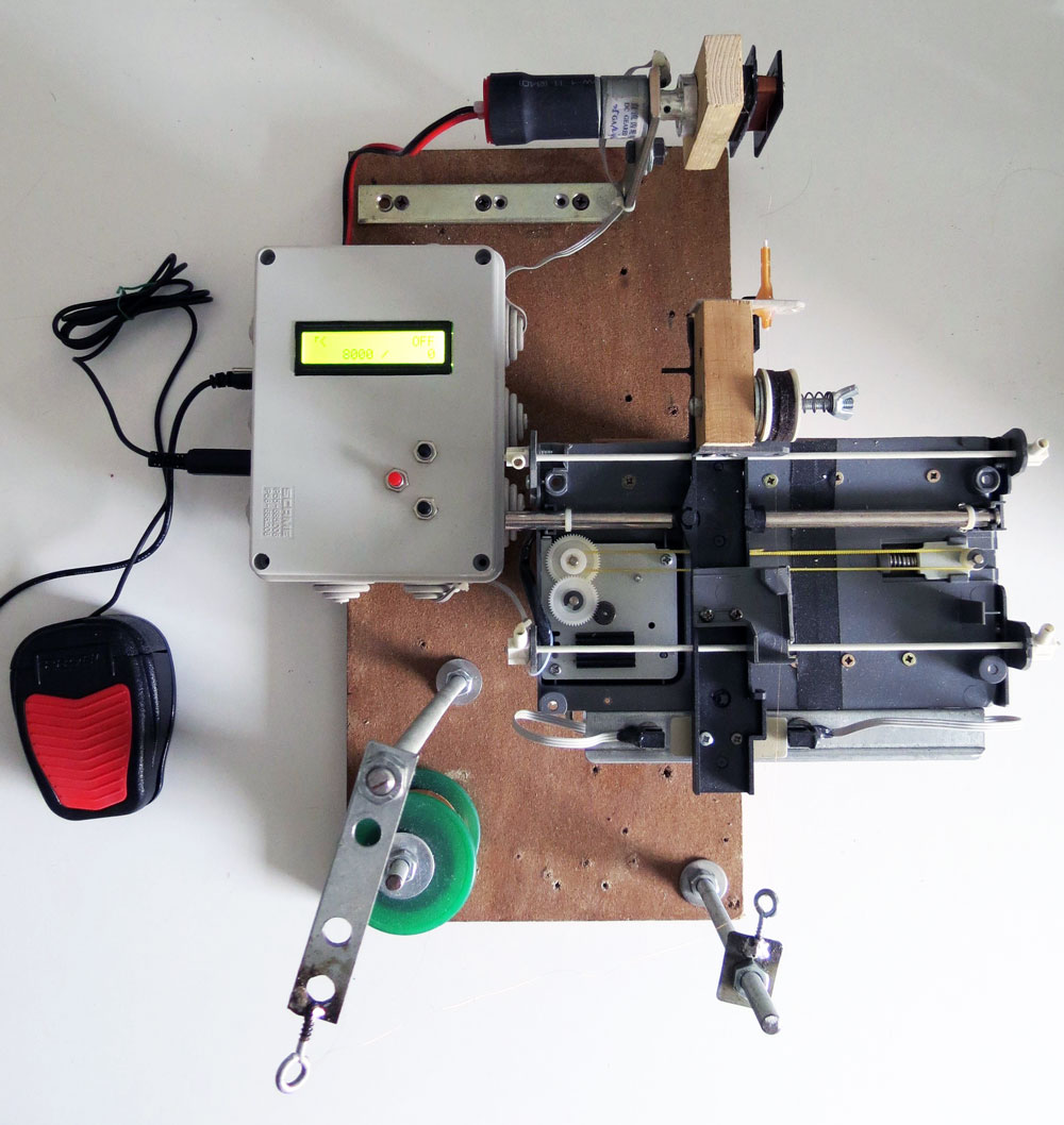
This project is a manual / CNC pickup winding machine, built on top of an ATmega8 microcontroller.
Characteristics:
- wind counter
- slow startup
- automatic stop
- configurable motor speed
- configurable winds
- 2 direction
- CNC automation
- configurable wire dimension (for CNC)
- traverse dynamic speed
- the current motor direction
- the rotating speed of your pickup
- the total and current wind counter
- the direction of the traverse mechanism
- the speed of the traverse motor
There are 3 buttons, SELECT, button UP and DOWN.
Short press SELECT to move to make the traverse motor move 1mm.
Long press SELECT to enter / exit programming mode. During the programming mode press button UP and DOWN to edit the selected value, short press SELECT to skip the next value, or long press SELECT to save new values and go back to running mode.
Short press button UP to change direction of the winding.
Long press button UP to reset counter.
Short press button UP to change direction of the guide movement.
Long press button DOWN to reset counter.

If you are in building mode, to make the wind start press the RUN pedal, it will start with a slow startup, to stop the winder release the RUN pedal.
The winding machine will automatically stops when the wind counter reach the configured number.
If you disable the autostop mode, the machine will always count wind, independently by the direction choosen.
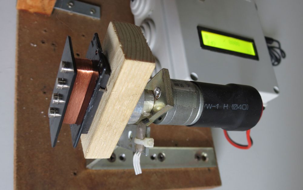
The winding motor used is cheap DC motor 12V 1200rpm, the motor driver is L298N chip board.
The traverse mechanism it is built using parts from a (broken) scanner, the guide motor is the stepper motor of the scanner.

Traverse mechanism has two limits. Limits are build using break-beam optosensos mounted on a small cilindric neodymium magnet.
That way guide limits can be moved depending on the pickup to be wired.
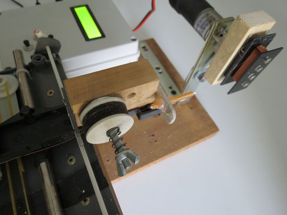
The wire tensioner it build using felts and a spring. It is simple but it works quite good.
The winding nozzle it's taken apart from a dental saliva ejector that my father (who is a dentist), gives me. It has a really small hole, and it's also built with plastic. This will not damage the wire we are going to wind.
The counter sensor it is built using a hall effect switch and a small neodymium magnet glued to the pickup holder.
Whenever the guide mechanism is changed, those constants has to be set GUIDEMOTOR_1STEPUM, GUIDEMOTOR_1MMSTEP, GUIDEMOTOR_1CMMAXSPEEDTIMEMS, GUIDEMOTOR_1CMMINSPEEDTIMEMS, GUIDEMOTOR_FIXEDSPEED_DEFAULT, WIRE_MINGAUGE, WIRE_MAXGAUGE
There are two calibration steps the user has to do:
- Measure the traverse distance moved per step. The GUIDEMOTOR_MEASURESTEP directive has to be set to 1, and the number of step to move has to be set in GUIDEMOTOR_MEASURESTEPSTEPS. Then the hex has to be compiled and uploaded. Now when you startup the machine, the guide will move for the desired number of steps. We measure the distance traveled. We compute the steps/mm as steps moved / total distance traveled. Than um/step is 1000 / steps/mm. Let's suppose we have set 20000 as step to move. If we have measured a traveled distance of 106mm, the step/mm is 188.879, and um/step is 1000/188.879, so 5.29. When done, set GUIDEMOTOR_MEASURESTEP to 0 again. Now we can set GUIDEMOTOR_1MMSTEP to step/mm value and GUIDEMOTOR_1STEPUM to um/step value.
- Measure the traverse maximum / minimum speed. The GUIDEMOTOR_MEASURESPEED directive has to be set to 1. Then the hex has to be compiled and uploaded. Now when you startup the machine, the LCD will show the max and min speed the guide motor takes to move 1cm. When done, set GUIDEMOTOR_MEASURESPEED to 0 again. Now we can set GUIDEMOTOR_1CMMAXSPEEDTIMEMS and GUIDEMOTOR_1CMMINSPEEDTIMEMS to the values shown on the display.
A guide step helper spreadsheet it is provided to help compute that values. The GUIDEMOTOR_FIXEDSPEED_DEFAULT, WIRE_MINGAUGE and WIRE_MAXGAUGE dimensions can be computed using this sheet.
You just has to fill values you already know, the values of your hardware.
You just has to fill values you already know, the values of your hardware.
The math to compute that values is also described as comments in the source files.
The maximum and minimum wire gauge it is an important parameter that defines what your pickup winder can wrap.
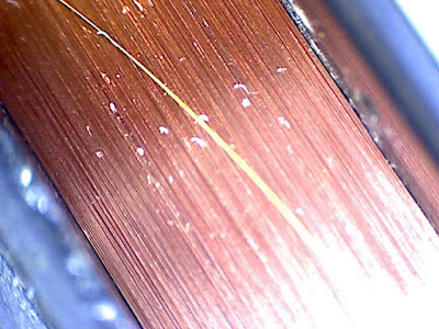
The winding pattern implement in this machine, is a simple traverse winding that places each wire wind next to the previous one.
See below and example of a pickup winded with this machine.
Things get's intereseting here, because the wiring motor doesn't always spin the same speed, take as example the "slow startup" stage, or when you decide to wire your pickup at a lower speed.
The guide motor is driven in a TIMER interrupt.
Here we set the steps that motor walk to position the cable,
We know:
We can compute how much space the traverse mechanism has to travel in order to place the wire next to the previus one, that's pretty simple.
number_of_winds = current_number_of_winds - current_number_of_winds
distance_to_wire = wire_gauge * number_of_winds
step_to_move = distance_to_wire / guide_motor_distance_traveled_for_1_step
Things get's a little complicated because i'm not using float math, so i've to record the remnant of the division.
number_of_winds =
current_number_of_winds - current_number_of_winds
distance(um)_to_wire =
wire_gauge(um) * number_of_winds + remntant_distance(um)_to_wire
step_to_move =
distance(um)_to_wire / guide_motor_distance(um)_traveled_for_1_step
remntant_distance(um)_to_wire =
distance(um)_to_wire % guide_motor_distance(um)_traveled_for_1_step
But that's not all folks, we also have to move the guide motor at such a speed that every wire is placed next to the other right when the pickup has done a full loop, I mean, we do not want a rapid guide motor travel, then a motor stop, then a rapid travel again, that movement has to be continous, and smooth, related to the pickup winding speed.
So, let's try to estimate that guide motor speed.
rotation_per_seconds = motor_rpm / 60
distance(um)_to_wire_in_1second = rotation_per_seconds * wire_gauge(um);
time(ms)_to_wire_1cm = (10000*1000) / distance(um)_to_wire_in_1second;
Now, the trick here it that we have previously recorded the maximum and minimum time in ms that the guide motor takes to move 1cm, so we can map the time we need, with that max and min speed.
speed = 100 - (time(ms)_to_wire_1cm - GUIDEMOTOR_1CMMAXSPEEDTIMEMS) * (100 - 1) / (GUIDEMOTOR_1CMMINSPEEDTIMEMS - GUIDEMOTOR_1CMMAXSPEEDTIMEMS) + 1;
That way we obtain a speed value from 1 to 100 for the guide motor to run smooth.
Enabling GUIDEMOTOR_DEBUGSTEPANDSPEED will display the current speed and steps left to run for the guide motor. This is a usefull during the debug stage. The speed will never exceed 100, and the steps left will never grow up. It it happens, it means that the guide is going too slow.

Future improvements will be implement an UART protocol to drive this machine by a PC, that way multiple wiring pattern can be simply performed.
This project was developed on Eclipse, built with avr-gcc on ATmega8 @ 16MHz.
Code
Notes
The maximum and minimum wire gauge it is an important parameter that defines what your pickup winder can wrap.
The winding pattern implement in this machine, is a simple traverse winding that places each wire wind next to the previous one.
See below and example of a pickup winded with this machine.

Things get's intereseting here, because the wiring motor doesn't always spin the same speed, take as example the "slow startup" stage, or when you decide to wire your pickup at a lower speed.
The guide motor is driven in a TIMER interrupt.
Here we set the steps that motor walk to position the cable,
We know:
- the number winds made from the last motor movement
- the current pickup rotation speed
- the wire gauge
- how many distance the guide motor travel for every step done
- the maximum and minimum time the guide motor takes to walk 1cm

We can compute how much space the traverse mechanism has to travel in order to place the wire next to the previus one, that's pretty simple.
number_of_winds = current_number_of_winds - current_number_of_winds
distance_to_wire = wire_gauge * number_of_winds
step_to_move = distance_to_wire / guide_motor_distance_traveled_for_1_step
number_of_winds =
current_number_of_winds - current_number_of_winds
distance(um)_to_wire =
wire_gauge(um) * number_of_winds + remntant_distance(um)_to_wire
step_to_move =
distance(um)_to_wire / guide_motor_distance(um)_traveled_for_1_step
remntant_distance(um)_to_wire =
distance(um)_to_wire % guide_motor_distance(um)_traveled_for_1_step
So, let's try to estimate that guide motor speed.
rotation_per_seconds = motor_rpm / 60
distance(um)_to_wire_in_1second = rotation_per_seconds * wire_gauge(um);
time(ms)_to_wire_1cm = (10000*1000) / distance(um)_to_wire_in_1second;
Now, the trick here it that we have previously recorded the maximum and minimum time in ms that the guide motor takes to move 1cm, so we can map the time we need, with that max and min speed.
speed = 100 - (time(ms)_to_wire_1cm - GUIDEMOTOR_1CMMAXSPEEDTIMEMS) * (100 - 1) / (GUIDEMOTOR_1CMMINSPEEDTIMEMS - GUIDEMOTOR_1CMMAXSPEEDTIMEMS) + 1;
That way we obtain a speed value from 1 to 100 for the guide motor to run smooth.
Enabling GUIDEMOTOR_DEBUGSTEPANDSPEED will display the current speed and steps left to run for the guide motor. This is a usefull during the debug stage. The speed will never exceed 100, and the steps left will never grow up. It it happens, it means that the guide is going too slow.

Future improvements will be implement an UART protocol to drive this machine by a PC, that way multiple wiring pattern can be simply performed.
This project was developed on Eclipse, built with avr-gcc on ATmega8 @ 16MHz.
Code
Notes
- read risk disclaimer
- excuse my bad english