Pages

Monday, December 15, 2014

A web configurable Xively logger, build on AVR ATmega328

Xively (formerly Cosm and before that Pachube) is a platform devoted to simplifying the interconnection of devices and data with applications on the Internet of Things. It is an on-line database service allowing developers to connect sensor-derived data (e.g. energy and environment data from objects, devices & buildings) to the Web and to build their own applications based on that data.


This embedded platform is a modular and configurable Xively data logger, built on an ATmega328 micro, usefull to send datapoints to your xively feed.


It has a network interface, so you can configure it using any browser, just pointing to the device address.
Network can be configured in two way:
  • Static IP, Gateway, NET Mask
  • DHCP
The Xively API Key and feed id can also be modified though the network interface.
Those parameters can be usefull if you want to build many devices with same sensors, and then connect it over different xively feed, without compiling and uploading a new hex.


Every sensor module can add one or more configuration parameter, you can implement it in the configuration modules files.

To make this platform easly expandable, the portion of code that gets data from sensor has been divided from the other code.
Every sensor module must "implements" (we are not using class here, but i'm using a object oriented term) some functions. Every sensor module, must be registered it in the checkdata.c file.
Every module must implements a set of function with strongly name rules, every function name must ends with a terminal string, depending on what the function implements. Of course even function parameters must comply with the one expected by checkdata.c file:
  • _init(void): called at startup to initize the sensor
  • _mstick(void): called every 1ms
  • _update(void): called every cycle to update the sensor data
  • _reset(void): called to reset the module
  • _xivelygetdata(char *): get the string data that will be posted to xively
  • _xivelypostret(enum checkdata_xivelypostretE): called after the data is posted to xively
  • _eeprominit(void): called if eeprom was never initialized
  • _eepromread(void): called on every starup to read sensor module eeprom parameter
  • _eepromwrite(void): called after data is saved
  • _wwwform(uint8_t[], uint16_t): get the html data that will be shown on the sensor network configuration
  • _wwwformret(char *): called on save of the sensor network configuration
As example, take a look at the checkdata_module01.c and checkdata_module01.h files, and their registration point on checkdata.c. Use the one provided as a startup point to create your own function module.

Other configuration parameters are available on main.h file.
The network sensor configuration page, can be enabled or disabled. Even the entire nework configuration can be enabled or disabled.

The hardware used is an ATmega328, running at 16Mhz.
The network board used is a cheap EC28J60 one.
Sample schematics is proposed above:


A PCB has been developed on top of the use of the Arduino Pro Mini board, to speed up the deploy of logger boards.
The full file are provided as dowload.


I'm actually using it from 2 years (it was previously named cosm logger), logging different things: air quality, solar water heating system. Mine is the one you can see below:


So i've written modules for many sensor:
  • temperature
  • AC current
  • luminosity
  • and many other

Code

Notes
  • read risk disclaimer
  • excuse my bad english

Friday, December 5, 2014

osCommerce to Amazon items synchronization

--ref 2012

osc2amazon is an osCommerce contribution which allow the synchronization from your osCommerce shop to your Amazon shop.
This contribution is completely web-based, it uses the amazon API to synchronize items.
It's released as an open source package under GPL license.


Download

Notes
  • read risk disclaimer
  • excuse my bad english

Monday, November 24, 2014

A Xively logger library for Spark Core

Xively (formerly Cosm and before that Pachube) is an on-line database service allowing developers to connect sensor-derived data (e.g. energy and environment data from objects, devices & buildings) to the Web and to build their own applications based on that data.


This library is a modular and configurable Xively data logger, built for Spark Core, usefull to send datapoints to your xively feed.

It comes with a configurable web page, user can set Xively API Key and feed id by browsing the setup page.

One can extend the sample snippet code to create a custom logger using sensors connected to Spark.


Code

Notes
  • read risk disclaimer
  • excuse my bad english

Friday, November 14, 2014

An op-amp based Electret Condenser Microphone Preamp for microcontrollers

This is an op-amp Electret Condenser Microphone Preamp board design for the use with microcontrollers ADC.


For the NPN version of this board, an for more information about microcontroller ADC and microphone input, please refer to this page:
http://davidegironi.blogspot.it/2014/11/a-npn-transistor-electret-condenser.html


The proposed circuit is just a revision of a pretty usually op-amp electret mic preamplifier.
The selected op-amp is the TLC272, because it can be drive in single rail operation, it's common mode input range, and has good noise performance. Also other op-amp could work.
The op-amp is configured in non inverting mode.


C3 is a power supply stabilization condenser.
R4 helps remove noise from the power line, but it can also be omitted.
R5 is used to polarize the microphone.
C5 is a low pass filter, it helps to remove board noise.
C4 is the input DC blocking capacitor.
R3 and R9 sets the circuit gain.
R9 loads the NPN collector.
R3 bias the signal using the collector feedback bias design, it prevents thermal runaway and stabilize the operating point, in conjuction wht R9 resistor, this sets the gain of the board.
C2 is a low pass filter.
C1 reduce dc "noise gain" by capacitively coupling the feedback, it also act as an high pass filter
R6 and R7 does a voltage divider to perform the bias on the signal.
C6, R1 and R2 also is an input voltage divider, and the cap here is is the output DC blocking capacitor, this design has input and ouput voltage diveder cause one can supply the opamp with a voltage, and the R6/R7 divider with the ADC reference voltage, with a single supply voltage, one can remove those last components.

Tested on ATmega8 and STM32F103 ADC, loaded with 5v or 3.3v (i'm using the C suffix TLC272 that has 3v as minimum recomanded), it has a little noise and it a good response even on low sound, sliglty better than the NPN version.

Wednesday, November 5, 2014

A NPN transistor Electret Condenser Microphone Preamp for microcontrollers

This is a NPN Electret Condenser Microphone Preamp board design for the use with microcontrollers ADC.


In order to make an electret condenser microphone signal "readable" by a microcontroller ADC, it has to be matched the ADC specification of the microcontroller. Most of the time it means, add some gain to the signal, reduce his impedance, and bias it.


Most microcontrollers ADC can convert signal from 0v to a their positive reference value.
So the input signal must be biased between the ADC max and mix voltage. Also, to obtain the maximum accurancy from the ADC, the signal should not exceed the max and min ADC voltage.
For ATmega8 with an ADC reference voltage of 5v, it means more or less at 2.5v, with an amplitude of 2.5v. Given the ATmega8 ADC accurancy of 10bit, that means 1024 points.

The proposed circuit is just a revision of a pretty usually NPN electret mic preamplifier.


C1 is a power supply stabilization condenser.
R5 is used to polarize the microphone.
C5 is a low pass filter, it helps to remove board noise.
C3 is the input DC blocking capacitor.
R9 loads the NPN collector.
R3 bias the signal using the collector feedback bias design, it prevents thermal runaway and stabilize the operating point, in conjuction wht R9 resistor, this sets the gain of the board.
C6 is the ouput DC blocking capacitor.
R6 and R7 does a voltage divider to perform the bias on the signal.

Tested on ATmega8 and STM32F103 ADC, loaded with 5v or 3.3v, it has a little noise and it a good response even on low sound.

Tuesday, October 14, 2014

Measure audio level using Root Mean Square on Spark Core

A Spark.io library to retrive RMS and Spl value from an audio input.


This library reads data from an ADC pin and returns the RMS value of the input simply using RMS avarage.
The root mean square (abbreviated RMS or rms), also known as the quadratic mean, is a statistical measure of the magnitude of a varying quantity.
Here is simply implemented by getting samples, for each of them making the root, then the mean for all the collected samples, and finally square the result.

This library is a derivation of the work you can find here: http://davidegironi.blogspot.it/2013/05/avr-atmega-audio-input-root-mean-square.html
So for more information about RMS, you can read the post above.


Code

Notes
  • read risk disclaimer
  • excuse my bad english

Thursday, October 2, 2014

Roland SP-404 AVR custom midi control pedal.

---ref 2009

The Roland SP-404 is a digital sampler made by Roland Corporation.
This sampler has an input midi port, and expose a set of midi commands to control the unit.


With this project user can control Roland SP-404 using a Midi Pedal.
With the pedal user can change the bank of the sampler and also switch on / off samples. It is a pedal extentions of the button matrix in front of the sampler.
Current working bank of the midi pedal extention it is show by a 7-segment digits display. User can work on the selected bank even if the SP-404 unit is showing other bank.


I've built it for a friend of mine, Mauro, which has this beautifull sampler, and want to control that unit even by his foot. This was my first project on Atmel micros. The design and the code was from 2009, actually it can be improved, can be also simplified, removing the shift registers and using a simpler button matrix on an ATmega, simoultaneos button press should be added, but at present it works and because it is open, you can change the code as you want.


I've no picture inside of the hardware cause it is already mounted. But i can post some picture of the external unit.

It uses an ATtiny2313.


Changelog
  • 03c: fixed schematics
  • 03b: fixed code double note out on press
  • 03: fixed schematics, clean code
  • 02b: fixed schematics
  • 02: first release

Code
Notes
  • read risk disclaimer
  • excuse my bad english

Tuesday, September 23, 2014

Measure brightness in Lux using BH1750 sensor on Spark Core

A Spark.io library for the BH1750FVI IC.


The BH1750 IC is a light intensity sensor module with built-in a 16 bit AD converter generating digital signal. With the BH1750 Light Sensor intensity can be directly measured by the luxmeter, without needing to make calculations.

This library provides function to measure lux through I2C on a Spark Core.


Code

Notes
  • read risk disclaimer
  • excuse my bad english

Monday, September 8, 2014

A DS18B20 1-wire digital thermometer AVR ATmega library

--ref 2012

updated to version 02

DS18B20 is a programmable resolution 1-wire digital thermometer.
It has an operating temperature range of -55°C to +125°C and is accurate to ±0.5°C over the range of -10°C to +85°C.

This library is an AVR implementation to retrive temperature from DS18B20.

Built using the reference document: "Using DS18B20 digital temperature sensor on AVR microcontrollers" by Gerard Marull Paretas, 2007.


You just have to select the port where the temperature sensor is connected.
This library was developed on Eclipse, built with avr-gcc on Atmega8 @ 1MHz.

Changelog
  • 02: fixed negative temperature readings
  • 01b: fixed schematics
  • 01: first relase
Code
Notes
  • read risk disclaimer
  • excuse my bad english

Monday, August 11, 2014

A pool cleaning robot custom electronic based on AVR ATmega8 microcontroller


updated to version 02

... Once upon a time, i had a working pool cleaning robot, then, it get's broken by the evil chlorine....

Chlorine damage a gasket on the robot and cause the shorts of the electronics embedded. It is obviouslly out of warranty, and the manufactuer does not send me any information to repair it, moreover a new board will cost me more or less like a new robot, cause i've to sent it to a certified repair center. For information only, original board was based on a dsPic.
So, i decided to get it back to life, replacing the electronics that gets damaged.


My replacement electronics it is based on ATmega8 micros.
The project is divided into two parts:
  • timer
  • cleaning robot
The timer contains the 220 AC to low voltage DC current, and it is out of water, his purpose is to start and stop the cleaning pool robot, which of course is inside the swimming pool.


The timer is an ATmega8 based countdown programmable timer, it is like the one you can find here: http://davidegironi.blogspot.it/2013/10/an-atmega-countdown-programmable-timer.html
It alternates a "working" period, and a "pause" periods. So i can run the robot at a predetermined interval of days, for an amount of minutes you can chose. Let's say for example 30 minutes every day.
It shows time using a double seven segment display. Periods can be selected from predefined values, stored in the firmware.
There are five buttons:
  • pause +/-: select the pause period
  • work +/-: select the working period
  • start and stop: iterate through perdiods.
Both period are stored into internal avr eeprom, so that if the main power goes down, user settings are restored at next bootup.


A green led indicates that the robot is working.
A red led it is used for over/under current detection: Indeed it may happens that something goes wrong, maybe one motor of the robot does not starts due to dirty. The timer checks the current consumption and evenetually stops the working period, until the next iteration.


The cleaning robot runs with two motor.
One that suck water from the bottom of the robot, the water then passes through a filter stage that cleans it, it also produce the suction effect that makes the robot climb the pool wall.
The other motor makes the robot move back and forth. Above the box of the movement motor.


The first one is a DC motor, it actually runs at almost 20 volts, the second is a brushless sensored motor.
The eletronics on the pool robot just drive the BLDC motor back and then forth for a period chosen semi-randomically that goes from 20 to 60 seconds. When the robot is running, the suck motor it is always on.


I've used a brushless driver i've previously implemented, you can find it at this addess: http://davidegironi.blogspot.it/2013/09/a-simple-brushless-sensored-motor.html
The board used for the cleaning robot is a ESC Mistery FM30A reprogrammed with my custom firmware. This ESC board is cheap, and use a ATmega8 running at 16Mhz.


In that way i can use a small and cheap brushless board, without soldering anything new, i just have to program it with my custom firmware to be indipendent.

It actually 1 years that works without problems.

You can fine code, hex and schematics, in the attached file.

Changelog
  • 02: added failsafe threshold to timer
  • 01: first release

Code

Notes
  • read risk disclaimer
  • excuse my bad english

Monday, July 14, 2014

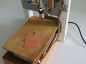
38mm x 38mm Laser Engraver build using CD-ROM/Writer on ATmega328p

A laser engraving machine, is a tool that uses lasers to engrave an object.


To build this tool I've used two old CD-ROM writer that lays around in my garage.
The X/Y positioning system it is build using the CD-ROM motor assembly. For the engraving laser i use the CD-ROM writer laser.
With this hardware the engraving area are will be almost 38mm x 38mm.


I know, there is nothing new in the project i posted here, this is just my implementation of a pretty usefull tool.

Warning! Laser diodes drive are emitting visible and invisible laser radiation and they are extremely dangerous! Their light can permanently damage the eyes. You must never look into the working diode even without the lens or point it on a reflective surface. Laser beam can cause burns or fire. This is usually a Class IIIb laser. Everything you do at your own risk.

The laser used is a red laser diode, taken apart from the DVD-ROM writer optics. It should be 100mA.
In CD-ROM and DVD-ROM you could also find IR driver, DVD laser writer diode will be a little more powerfull than the CD one.
Laser diode usually has three pins, one is the common ground, laser and photodiode cathode (-), one the laser diode anode (+), the other is the monitor photodiode anode(+).
If the diode you are using has no mark, and you do not know the diode pinout, you have to find the laser cathode and anode. One simple method I use is to power up the diode with a 1.8 to 2.2v current, just for a little amount of time, let's say 1s, if it sucks current, that wiring is the laser diode pinout.


Laser diode has to be drive with a proper driver, to run mine, i've used a small and cheap LM358 based adjustable driver, capable of 10mA to 400mA, it also comes with a TTL input pin to enable or disable the laser. You could also use a LM317 to build a simple laser driver, there are many schematics around here, that exaplains how to build one.
A standard 80mm x 80mm pc brushless fan is installed to clear the smoke, this prevents the laser optics lens to be clouded.


The two motors are small stepper, to drive the motors, two EasyDriver stepper driver are used. EasyDriver is a Allegro A3967 based driver board. Motors are powered at 5 volts.
Once again, if you do not know the motors wiring, you have just have to pay attention to pair each coil and then connect to the EasyDriver motor output. If direction is inverted, invert the coil wiring, or just setup grbl to invert the axis direction.


The microcontroller used here is an ATmega328p running at 16Mhz. I've used an Arduino Mini board, even if the software does not use the Arduino framework. The software used is grbl, available at http://github.com/grbl/grbl, which is a powerfull yet opensource g-code parser.
I'm using grbl version grbl v0.8c (ATmega328p, 16mhz, 9600).
You just have to upload the firmware using your favorite uploader, the grbl wiki page drive you on how to do this step.
On the grbl wiki page you could also find any other information about command and software setup.

Commands to the engraving machine are sent through UART.

When you assembly your harware, pay attention to build it making X normal to the Y axis. The two direction has to be perpendicular, or your engraving will has distorsion.

Below you should find the schematics i'm using.


One you have connect and upload the grbl firmware to your microcontroller, you could use terminal software, or a grbl controller to setup your board. I'm using Grbl Controller to setup and send command to grbl, but you can also use a simple terminal.
Below you can find the grbl configuration parameters i changed, basically what i've changed here is:

Set step/mm to setup the correct motor distance to run (a common step/mm value for CD-ROM motor should 53.333):
$0=53.333 (x, step/mm)
$1=53.333 (y, step/mm)
Set the accelleration value to 100:
$8=100.000 (acceleration, mm/sec^2)
Enabled the homing cycle:
$17=1 (homing cycle, bool)

If you need to invert axis direction, "Step port invert mask, int:binary" is the paramenter you have to touch. Those are the most common inversion, but if you need other inversion, look at the grlb wiki for this parameter:
$6=32 (invert x axis)
$6=64 (invert y axis)
$6=96 (invert x and y axis)

To test it, just send the
X10 Y10
command, or use the Grbl Controller rows, you should see a 10mm movement on each axis.

Also check the "spindle on" command power your laser on and off.

Now you could be able to send g-code drawing to your engraver.


There are a lot of software you could use to build g-code draw, the one I use the InkScape.
The working are for this plotter is 38mm x 38mm, so setup your project area to this dimension.
Once you have you path, then you could select the path you want to engrave, and transform it using the InkScape laser engraver extension.
Just copy the extension on your extension inkscape folder, restart inkscape, and use that to build your g-code file.
Once you have your g-code file, you could send it to grbl using Grbl Controller, or other software like Universal-G-Code-Sender.

Notes
  • read risk disclaimer
  • excuse my bad english

Tuesday, July 1, 2014

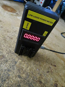
A cheap and simple Laser Power Meter LPM for small power source

A Laser Power Meter (LPM) is an instrument that measure the energy output of laser beams.
This project is my way to implement the MarioMaster LPM meter. You can find further information about this design in laserpointerforums.com the post here: http://laserpointerforums.com/f42/diy-thermal-lpm-under-50-a-51129.html

Warning! Laser diodes drive are emitting visible and invisible laser radiation and they are extremely dangerous! Their light can permanently damage the eyes. You must never look into the working diode even without the lens or point it on a reflective surface. Laser beam can cause burns or fire. This is usually a Class IIIb laser. Everything you do at your own risk.


This type of meter uses a ThermoElectric Cooling module (TEC) to measure the power of a laser. The TEC will absorb the laser light, and transform the heat generated by the laser beam to an electrical signal.
An operational amplifier is used then to amplify the signal and ouput it to a volt meter.
Voltage meter will display the power in W unit of the laser beam you are testing.
The TEC takes a little amount of time to heat, so wait until your reading became stable.


This type of meter is simple and cheap to build.
It can measure laser power up to 2W, with an accurancy of +-10mW.


You have to use a "small" (< 20mm x 20mm) TEC, for my circuit i've used a 6.6mm x 8.3mm TEC, Laird OT18,18,F2A 0608 HWS20mm.
TEC should be glued to an heat sink, and then paint with black to absorb laser beam of any frequency.
In my project the selected opamp is a common LM358. Only one channel of the opamp is used, the other is connected just to remove noise.
As a voltage meter use a any DC 0..5V Volt Meter with 3 digit precision at least.
As a power source, just use a 9v battery or any DC source.
Trimmer are used to calibrate the meter, multiturn trimmer are preferred.


Once you have build the circuit you have to calibrate it.
Power on your unit, and use the ZERO trimmer to adjust the volt meter to zero. Note that this step can be skipped if you use voltage meter with auto zero calibrating mode.
Heat the TEC with a laser with a know power, let's say 100mW. Wait until your reading are stable, then adjust the voltage meter output using the GAIN trimmer to fit the laser power source.

I've used a 100mW red calibrated laser to calibrate this meter.
Then i've tested it with a 200mW laser, and a 20mW (the one of the video) without problems.


Notes
  • read risk disclaimer
  • excuse my bad english
Monday, June 23, 2014

Homemade lap steel guitar


The lap steel guitar is a type of steel guitar, an instrument derived from and similar to the guitar. The player changes pitch by pressing a metal or glass bar against the strings instead of by pressing strings against the fretboard.


This is my homemade lap steel guitar.
It is built using a 6.5cm x 4.5cm x 85cm piece of wood taken from an old pallet, then planed and sanded.
The action is 1cm height. Bridge and nut are built using L shape aluminium bar of 1cm x 1cm. An additional aluminium bar is mounted and perforated to lead strings out of the nut to the tunings pegs. Nut and bridge has string slot. Strings are 1 cm apart from each other.
Tunings pegs are standard electric guitar pegs.


Sound is amplified using a stratocaster model like pickup, at 5cm from the bridge. It has 2 250pots one log and the other linear, used for tone and volume.
Fret reference are drawn on the wood, before the transparent lucid finiture paint was given.
The scale is 22 1/2".

Scale length 571.5mm 22.5"
FretDistance (mm)Distance (inches)
132.081.263
262.352.455
390.933.580
4117.904.642
5143.365.644
6167.396.590
7190.077.483
8211.488.326
9231.699.121
10250.769.872
11268.7610.581
12285.7511.250
13301.7911.881
14316.9312.477
15331.2213.040
16344.7013.571
17357.4314.072
18369.4514.545
19380.7914.992
20391.4915.413
21401.5915.811
22411.1316.186
23420.1316.541
24428.6316.875
25436.6517.191
* Distance is measured from the nut

About the video: this is my first lap steel guitar, I've never played one, so i've to to practice a little more to play it better, but that's just a demo video.


Notes
  • read risk disclaimer
  • excuse my bad english

Monday, June 9, 2014

Drum light trigger that uses leds, a NE555 timer and a piezo transducer

This circuit is a Drum Light Trigger.


It uses a piezo transducer that reacts to drum vibration, and a NE555 timer to setup the light time.
There are two trimmer pot, one to setup the sensibility of the vibration, the other to set how long the LED light will be active.
This design is a small makeover of a circuit i've printed from an online image, unfortunately i can not recover the original author.


About the video: The piezo is attached to kick drumhead, and the led strip is inside the kick. I'm not a drummer, so there may be many imperfections in the way i play, but it's just a video to show you how this drum trigger wors. I've just add some synthesizers and guitars to make it sounds better. For those how are interested in, it is recorded using one wm-61a phantom powered condenser mic, and then processed a little using the Reaper digital audio workstation software.

Find the attachment schematics below.


Notes
  • read risk disclaimer
  • excuse my bad english

Saturday, May 17, 2014

A Pickup Winding machine built on an ATmega8

A pickup winding machine it is used to wind a guitar pickup.


The core of this project is an ATmega8.

It features:
  • wind counter
  • slow startup
  • automatic stop
  • configurable motor speed
  • configurable winds
  • 2 directions
If you are looking for a CNC version: you can find it here: http://davidegironi.blogspot.it/2016/06/a-cnc-pickup-winding-machine-built-on.html

This winder has an LCD display that will show
  • the current motor direction
  • the rotating speed of your pickup
  • the total and current wind counter

You can also setup:
  • motor direction - clockwise, or anti-clockwise
  • direction of the wind counter to increase - clockwise, or anti-clockwise
  • motor max speed - from 1(min) to 100 (max)
  • motor startup accelleration - from 1(min) to 100 (max)
  • numbers of wind - from 1(min) to 99999 (max)
  • auto stop mode - manual mode, or stop when all winds are done
There are 3 buttons, SELECT, button UP and DOWN.
To enter the programming mode, just long press SELECT button.
Press SELECT once to change the programming parameter, button UP and DOWN to edit the selected value, then long press SELECT again to save new values.


If you are in building mode, to make the wind start press the RUN pedal, it will start with a slow startup, to stop the winder release the RUN pedal.
Long press butto UP to change direction.
Long press butto DOWN to reset counter.
The winding machine will automatically stops when the wind counter reach the configured number, and it can goes less than zero
If you disable the autostop mode, the machine will always count wind, independently by the direction choosen.


The motor used is cheap DC motor 12V 1200rpm, the motor driver is L298N chip board.

This library was developed on Eclipse, built with avr-gcc on ATmega8 @ 8MHz.


ChangeLog
  • 01b: fix a circut file typo error in the LCD connection of previous version.
  • 01: first version.

Code

Notes
  • read risk disclaimer
  • excuse my bad english

Saturday, May 3, 2014

A .NET WinForm DataGridView with advanced capabilities

This components is a .NET WinForm DataGridView with advanced capabilities, it is an extention of the .NET WinForm DataGridView.


The project is a refactoring of "Advanced DataGridView with Excel-like auto filter" you can find here: https://adgv.codeplex.com.
The author, also post this as a patch in the project page.

This Enhanced DataGridView components features:
  • Ascending or Descending Sort order for any column, by code or run-time
  • Filter any column using a Custom Filter, or selecting values from using an Excel-like Filter List view, using also an advanced feature for DateTime types
  • Saving and Restoring preset for Filter and Sort
  • Enabling or Disabling Filter and/or Sort features for any column,by code or run-time
  • Search ToolBar to find values in columns
A Sample project is attached in code to test this DataGridView.

It is written using Microsoft Visual Studio 2012, using the .NET 4.0 framework.

Copyright (c), 2014 Davide Gironi <davide.gironi@gmail.com>
Original work Copyright (c), 2013 Zuby <zuby@me.com>
This project is licensed under the Microsoft Public License (Ms-PL), see attached LICENSE file for further information.


ChangeLog

  • 1.0.x.11: fixed DateTime filter problem
  • 1.0.x.10: fixed AdvancedDataGridViewSearchToolBar problem with not Visible column search
  • 1.0.x.9: first release


Code

Notes
  • read risk disclaimer
  • excuse my bad english

Tuesday, April 22, 2014

AutoBuild is a build automation tool for Visual Studio

Updated to version 1.0.2.2

AutoBuild is a build automation tool written using PowerShell on PSake.


It is usefull to automate the Visual Studio processes of:
  • Build
  • Clean
  • UnitTest
  • Release binary
  • Release source
  • Version number updating
It can be configured using the AutoBuilder.config.ps1 file.

You can find the tool code, and a sample project in the download link below. The sample configuration file is pretty explicative, you will find instruction on how it works as self-contained comments.

Changelog

  • 1.0.2.2: updated test procedure
  • 1.0.2.1: fixed SDK versioning
  • 1.0.2.0: added support for SDK type solutions, see Upgrade instructions in readme.txt file
  • 1.0.1.9: minor fixed
  • 1.0.1.8: fixed a problem with Windows 10 and robocopy parameter, added the .vs exclusion to src file release
  • 1.0.1.7: fixed the AssemblyInfo.cs version update method
  • 1.0.1.6: improved the release folder management, now release are organized in subfolder; added some usefull build scripts
  • 1.0.1.4: add remove building folders (bin and obj); added the build debug and release facility; improved the version numbering update method
  • 1.0.1.3: first release


Code

Notes
  • read risk disclaimer
  • excuse my bad english