Pages

Tuesday, December 6, 2022

Video intercom additional buzzer circuit


My parents has to change their doorbell. They have one 90's audio only doorbell with multiwire connection.

We buy a new video doorbell. It's the Vimar K40910 Kit.
This doorbell cames in two parts: the external unit and the internal monitor unit.

30 years later the intercom of my parents, devices talks using a on a two wire protocol, that is fairly better from the installation point of view, but worst in terms of extentions.

I would like to add a couple of additional buzzer. This new intercom does not have any connection for additional speaker ring. It's time to find a way to add this output.

The ring I would like to add are simple 12V buzzers. I basically need to close a switch for a certain amount of time whenever the doorbell button is pressed.

First try was to reverse engineer the two wire protocol. It happens to be a 24V two wire DC protocol, with modulation on high frequency. My 50Mhz scope could barely catch the modulation. That means I would have to get it using an FPGA or a micro with a decent speed. I try to make thinkgs simple, so my Plan B take action.


 On the external unit the button is connected to a 5V and a GND route. I suppose the 5V is a pullup connection to the unit microcontroller.

First try was to use this pullup voltage to engage the led of an opto-coupler. I fail. That's because the voltage drop across the led also drop the voltage under the threshold for the microcontroller of the external unit.

So I decide to use a comparator. I find a 12V line from the external unit. I use the 12V to drive an op-amp (LM358) in comparator mode, comparing GND with the pullup line. Then the signal is inverted using a NPN transistor (2N3904). I use this signal to drive an opto-coupler (PC817)

On the other side of the opto-coupler I have to put the timer circuit. Cause I want the rings to emit sound for a certain time after the unit button is pressed. I've used a common NE555 timer circuit. I've just to select the right resistor and cap to obtain a timer from less than 1 to more than 30 sec.

The buzzer are driven by a N-Channel Mosfet with the gate connected to the NE555 output.

This small circuit is now ready to be soldered on protoboard. It fits the enclosure of the external unit mounting, the 12V that drive the buzzer are taken from an additional power supply and I can use the multiwire cable that was previously connected to the old intercom.

Find the circuit for this small project below:


Notes

  • read risk disclaimer
  • excuse my bad english


Thursday, November 3, 2022

MiniProto, a mini protocol for data exchange between devices


MiniProto is a mini protocol for data exchange between devices.

It is build and tested over the serial communication protocol, but it can be ported to others.
It is designed to send strings and byte arrays.
MiniProto in the current implementation you can send up to 999 commands, and 999 byte long byte array.


The command structure is the following:
STX|ACK|NAK CMD LENGTH DATA CRC ETX

Command parts are:
  • STX (hex 0x02): command begin 
  • ACK (hex 0x06): acknowledgment command begin
  • NAK (hex: 0x15): negative acknowledgment command begin
  • CMD: 3 byte, ascii number, command number
  • LENGTH: 3 byte, ascii number, length of data
  • DATA: byte array
  • CRC: 1 byte CRC code
  • ETX (hex 0x03): command end
Send command can request an acknowledgment to be sent back. The acknowledgment command must contain the command number, and must start with ACK or NAK byte.

The ESC special char (hex: 0x1B) is used as escape character. Indeed if a ETX byte is sent in DATA, it is preceded by the ESC character. The escape character reduce the max length of DATA. An alternative strategy to prevent the use of the ESC character is to use the LENGTH field to read data, instead of using a read to ETX character. This may be implemented in a future version of this protocol.
Each command must have a CRC hex byte, this prevents communications errors.
CRC function is CRC polynomial x^8 + x^7 + x^2 +1  implemented using a lookup table to speed up the computation process.


DATA max length, and protocol timing can be personalized in the header file of the protocol.

Errors in communications may happens, due to timing or interference. However I'm using this protocol with decent results.

On the embedded side, there are two ways this protocol process input data.
A "blocking" one, and a "timed" one.
In the blocking way, the called functions try to read input from the selected channel, that is UART in this example. If a char is read, then the next one is processed, till the the end of protocol command, or till the threshold time passed.
In the timed way, two function are involved, one that read characters, and another that can be called to get the last command found. Most of the works is done inside the read/input function. This function read one, or up to a threshold bytes until the end of protocol command.
On both function a few other error preventing mechanism are implemented.
The timed functions most of the time it's the way to go, cause it does not stop the working loop that much. One can even put this function in a TIMER, and use the read last command function in the program loop.

I've tested this protocol on AVR ATmega8 running @8Mhz.
A NET C# client library is implemented for test.


Code

Notes
  • read risk disclaimer
  • excuse my bad english

Monday, October 3, 2022

1W Guitar Amplifier in a 60's portable radio case

 I've found a junked 60's portable radio by Harmonius, which it used to be a small Italian manufacturer.

I like the shape of the radio, so I decide to use it.

Unluckily the back case of the radio is broken, so I have to replace the back with a wooden wine box case.
Have to cut the front retain plastic on both side, and glue a couple of pieces of wood to make the front fit the wood.
Then I paint the wood and apply wax.


Inside I've put just a little bit of filter fabric of a cooker hood.

I've reused the original PCB as support for the supply, and for the tone control.

Also, I've reused the main transformer, which is a 230V to 12V AC. The supply is regulated to 9V using a 7809 with an heatsink and a couple of capacitors.

The main amplifier board is build araound a LM386 IC. The schematic is based on the "Ruby Amp", with a little bit of mods.

A tone control, mounted on the tuner pot, is added.

The volume is mounted where the original radio volume was.

Two selectable buttons where used for: Clean/Overdrive selector and Overdrive/Distorsion selector. This last one is enable only if the Overdrive channel is selected by the first switch button.

The original speaker was fixed using a little bit of casting plastic.

The end result was a mini 1W amplifier that is pretty looking.

Last but not least, I've found a bounch of germanium transistors inside this radio, I'm happy I've saved those two from junk.

Notes

  • read risk disclaimer
  • excuse my bad english

Thursday, September 8, 2022

A4 home-made Laser Engraver firmware update Grbl 0.9 to Grbl 1.1h

 A few year ago I've build a Laser Engraver out of a an old scanner and an old printer.

This laser engraver it's based on grbl (https://github.com/gnea/grbl) version 0.9. I would like to update the software I use for engraving, moving to the new version of LaserGRBL (https://lasergrbl.com/).

You can find my blog post about this scanner here: http://davidegironi.blogspot.com/2015/12/a-diy-a4-laser-engraver-made-from.html

LaserGRBL software is really easy to use, also it has the SVG to G-Code function, that makes the print process really easy.

Warning! Laser diodes drive are emitting visible and invisible laser radiation and they are extremely dangerous! Their light can permanently damage the eyes. You must never look into the working diode even without the lens or point it on a reflective surface. Laser beam can cause burns or fire. This is usually a Class IIIb laser. Everything you do at your own risk.

I'm updating to grbl 1.1h. You can find releases hex in the grbl page, unluckily in order to use grbl for a 2 axis laser engraver like mine, you have to recompile the grbl binary, making some changes to the config.h file.

You have to change the homing procedure. Just edit the config.h file commenting out the following lines

//#define HOMING_CYCLE_0 (1<<Z_AXIS)                // REQUIRED: First move Z to clear workspace.
//#define HOMING_CYCLE_1 ((1<<X_AXIS)|(1<<Y_AXIS))  // OPTIONAL: Then move X,Y at the same time.

then add the two lines below:

#define HOMING_CYCLE_0 (1<<X_AXIS)  // COREXY COMPATIBLE: First home X
#define HOMING_CYCLE_1 (1<<Y_AXIS)  // COREXY COMPATIBLE: Then home Y

Also, if you like me do not have a variable power laser driver, you should comment out the following line in order to disable the variable spindle capabilities

//#define VARIABLE_SPINDLE

Now, just follow the Compiling Grbl instructions you can find here: https://github.com/gnea/grbl/wiki/Compiling-Grbl. Eventually you can upload the generated firmware to your hardware.

It's a simple process, but to make things easyer for you can find my compiled hex below, it's compiled for Arduino Micro board with ATmega328.

Now you should be able to use your grbl software.

First thing you have to do is update the default grbl settings, I'm using the one below. Please note that you have to compute at least your motor/mm steps to update the settings. You can find instruction on my blog post linked above, or searching on the web for this.

Just for sake of information, find below my grbl settings:

$21 = 1         (hard limits, bool)
$22 = 1         (homing cycle, bool)
$23 = 3         (homing dir invert mask:00000011)
$27 = 5.000     (homing pull-off, mm)
$100 = 37.975   (x, step/mm)
$101 = 94.956   (y, step/mm)
$110 = 100.000  (x max rate, mm/min)
$111 = 100.000  (y max rate, mm/min)
$130 = 212.500  (x max travel, mm)
$131 = 274.400  (y max travel, mm)

Last but not least, in order to use LaserGRBL on an engraver without the laser PWM modulation (i.e. VARIABLE_SPINDLE disabled), you have update the software settings disabling the "Support PWM" checkbox.

Done, you should now be able to engrave your SVG files.

Notes

  • read risk disclaimer
  • excuse my bad english

Wednesday, August 10, 2022

DentneD (Dental Practice Management Software) video update

This post is follow up of this post here http://davidegironi.blogspot.com/2018/07/dentned-open-source-dental-practice.html: about the DentneD open source Dental Practice Management Software

Here you can find a video that explain the basic functions of dentned.


You can find DentneD here: https://github.com/davidegironi/dentned

Notes
  • read risk disclaimer
  • excuse my bad english

Wednesday, July 6, 2022

DoctcoD: an open source Medical Practice Management Software


DoctcoD is a Medical Practice Management Software.

It is free, released under Open Source license.


You can trace your patient, treatments, scheduling appointments, doing reports, and billing management. It features a client-server architecture. 

It features a client-server architecture.

You can trace your patient, treatments, scheduling appointments, doing reports, and billing management.

It features a client-server architecture.

Features:

  • Doctors records, manage more than one dentist
  • Patient records
  • Full patient medical records
  • Patients attachments and notes management
  • Billing management, with invoices and estimates
  • Treatments lists
  • Scheduling agenda
  • Customizable reports
  • PDF output templates
  • Cloud backup scripts
  • Calendar and patient treatments web interface
  • Client-server architecture, access by multiple computer at the same time
  • Multilanguage
  • Send appointments reminder
  • Password form protection
  • Windows service for additional features

Requirements:

  • Microsoft Windows with .NET framework 4.5.2 or later
  • Microsoft SQL Server 2012 or later
  • For web app: PHP 5.3 or later


Code & Releases

Notes
  • read risk disclaimer
  • excuse my bad english

Thursday, June 2, 2022

Antonelli COMET 2616 80's organ repair


The Antonelli COMET 2616 is a 61 key organ.

Antonelli was an Italian company, established in 1935. During the 80's the Antonelli mostly builds kids learning music instruments, luckily they also have built some instrument, not for kids. Mine is one of those.

Before taking to my home lab this keyboard, I've checked the keypad, to my surprise I've found something with a good key action, so I decided to give this keyboard a try.

General conditions are not good, wood is broken here and there, and keyboard was opened with parts flapping around in the breeze.

First try was to power it on. It does not work.

It turned out it was simply the fuse.

One turned on, I've to replace the speaker. Someone already have removed the original one and replace with a speaker from a TV, since the speaker hole is round but the speaker itself is rectangular shape. Also they hole the wood probably to mount another speaker. By the way, the speaker foam was done.

I've attached a test speaker, now the keyboard sounds, but many buttons and key does not respond well. Oxidation has made his job.

Cleaning buttons and keypad was a bit tedious, but has to be done. I've disassembly the whole keyboard. Both buttons and key has been built using spring contacts.

I've cleaned the contacts using isopropilic alcohol, a toothbrush and a rag. Then I've used some contact cleaner spray using brush and rag.

A better approach should be desolder al the contact, putting all the spring in an aluminium foil, and boil them in salt water. This will reduce silver oxide back to silver, production sulfur hydroxide. Anyway, this time just cleaning it without the complete process did the job, now buttons and key works well.

For the wood, at first I've repaired broken wood with vinylic glue. Then the torn veneer using mastic glue by Bostik. I then I've use some wood filler, and finally I've paint using wood finish just where I repair the wood.

Another piece to repair was the speaker, for that I've removed the horrible holes for the secondary speaker. Instead I've made a nice squared hole, and prepare a piece of wood where I mounted a tweeter. Then I mount the woofer on the main speaker housing.

I've decide to build also a pair of legs for this organ, and sheet music holder. I've wood panels from a wardrobe that I could use, so I take three of them, and use for left and right leg, the third I've used to join the legs. Now the stand is solid and can keep the organ.

I've used the same wood for the music sheet holder.

Now let's talk about the keyboard specification. The keyboard has a RHYTHMS and a ACCOMPANIMENT section with a few rhythms like Rock, Disco, Bossa Nova... and so on. The accompaniment section has the ability to split the keyboard and enable Bass and Chords mode on the left side. TEMPO is a slider potentiometer. The SOLO section is built up on 6 different sounds: FLUTE 16", FLUTE 8", FLUTE 4", PERC 4", BRASS and STRINGS. If enabled each register can sound while the other is enabled, this allows a few interesting sound. Other three sounds are located in the PRESETS section: PIANO, VIBER and PAN FLUTE. EFFECTS like SUSTAIN, LONG (sustain), VIBRATO, DELAY and PHASER can be switched on.

The finished product looks very pretty and sound good too. There are not many sounds available, but the keypad quality is pretty good, and the ability to enable more than one register gives me the change to build up a few pretty sounds. This is definitely not a toy.


Notes
  • read risk disclaimer
  • excuse my bad english

Sunday, May 8, 2022

Seven segment smart counter PCB and 3D printed box


I've introduced you my seven segment RESTful counter here: http://davidegironi.blogspot.com/2020/04/esp8266-seven-segment-counter.html
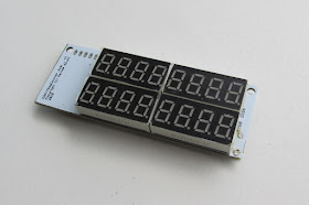
It's based on the ESP8266, and it may drive one or more 8 digits seven segment MAX7219 displays.

In this post here I would like to share with you a double line 8 digits seven segment PCB board. Ready to be printed and builded.


Also, I attache here the CAD files that you can use to print you own box for this counter.

The board was built using Eagle.
The seven segments module that i use are the HS420361K-32, which is a common cathode module with the following wiring.

  pin 01: E
  pin 02: D
  pin 03: dp
  pin 04: C
  pin 05: G
  pin 06: dig4
  pin 07: B
  pin 08: dig3
  pin 09: dig2
  pin 10: F
  pin 11: A
  pin 12 dig1


Please find the connection diagram below. Of course the wiring of 4 bit seven segment modules changes by the model you use, so pay attention to your wiring scheme.


The box was designed using Autodesk Fusion 360 and printed using a Creality3D Ender-3 Pro on PLA.

Code
Notes
  • read risk disclaimer
  • excuse my bad english


Saturday, April 2, 2022

Garrard 60B by Philarmonic Elettronica turntable repair


I've found a 70's turntable. Of course it was not working, so I decide to repair this piece of gear, mostly because I do not have a turntable, even if I have a few vinyl, and cause I would like to learn how a turntable works.

Mine it's a Philarmonic Elettronica turntable, based on the Garrard 60b mechanism. The core of the player is indeed the Garrard gear. Garrard Engineering and Manufacturing Company was British company that sold turntable and also mechanism used for other companies.

The Garrard 60B is a 3 speed auto-player with single play facility, it can runs at 33, 45 and 78 rpm.

My disc spins, but really slowly even at 45rpm. It needs to be cleaned. Also the auto-player mechanism does not works, and the stylus is completely broken.

The wood is in pretty good condition, I just remove the Garrard mechanism and clean it apart.

To clean the mechanism I use water and degreaser. Then I clean it all with water and let it dry. Once dried I disassemble the plate, it turns out that the gear in charge of the auto-player mechanism has a decent amount of grease that dried out during years, this lock the gear not allowing it to spin. I clean it all.

Then I use oil (5W 30 motor oil) and grease (lithium grease) to lubricate gears. I use grease, just a little, on just a few points, for the most of the parts I use oil, just a few drops.

Once assembled again, all work smooth.

Now it's time to fix the style. Original one as said was fully broken, the repair cartridge costs more than 15Eur, so I decided to look for a cheaper one. I've found a couple of cheap stylus for 3Eur shipped.
I've just to draw and print in PLA an adapter. Once done the stylus is mounted and worked well.

Now, I have also a spare old transformer around, so I decide to buy a phone preamplifier. Unluckily I've to change values for two resistore of the input voltage divider of this preamplifier, cause the new cartdridge has high output, and this leads to distortion if the gain is not reduced. I must admit that my AIWA amplifier phono preamplifier sounds better that the integrated board I've used, but that will be enough if I've to use with an amplifier without phono preamp. 

Then I wired all using a 4PDT switch with two position:

  • position 1, preamplifier detached: L/R channel from stylus output goes straight on the output
  • position 2, preamplifier attached: L/R channel from the stylus to the input of the preamplifier, then output of the preamplifier connected to the output cables

This way I can use the turntable even with an amplifier without phono input.

Also I've add a couple of led, on the bottom of the plate.

Last thing that I've build is the top enclosure, I didn't want to use plexiglass for the cover, so I've used wood. Then I've glued on top of the fabric, using vinylic glue, to stay in the same context :)

The result it's a fully working, vintage style turntable, equipped with new era cheap stylus and a phono preamplifier.

Notes

  • read risk disclaimer
  • excuse my bad english

Tuesday, March 1, 2022

D04: vintage 18W guitar amplifier


The D04 is a guitar amplifier built using an old turntable by Perpetuum Ebner (https://de.wikipedia.org/wiki/Perpetuum-Ebner).


The model I've used it's a vintage 70's PE 3015 turntable. When I was a boy friends give away this turntable to me, cause it's not working. I've used this turntable years ago as a standard amplifier, taking advantages of it's aux input, then I've decided to turn this in a guitar amplifier.

Like the D03 amplifier that you can find here http://davidegironi.blogspot.com/2020/03/d03-lesa-boogie-guitar-amplifier.html, this one also is built using a dismissed and not working turntable.


Building technique of the case was almost the same. The speaker were glued together and an hole was drilled in order to makes cables run one side to the other.
I've worked then on the turntable panel to make it fit the top of the speakers.
As on the D03, I've used all the original potentiometer knobs as the panel holes.
The power switch is on the top of the panel.
Then a channel selector is installed.
This amplifier has 2 channels
  • clean
  • overdrive/distortion
The selector switch from the clean to the overdrive/distortion channel. Also the switch act as a voltage divider selector for the overdrive/distortion section. The selected transformer, this time is a 24V single rail, think it's a 40VA. Single rail are cheaper and easier to find than dual rail, so I would like to build something with a single rail.


The preamplifier it's a JFET preamplifier based on the J. Donald Tillman design found in the article "A Discrete FET Guitar Preamphttp://www.till.com/articles/GuitarPreamp/. It use a single J201 JFET and just a few components. It really sounds good. This kind of preamplifier is the same you can find in many other amplifier.

Then the tone stack is a dual tone, as i tell you I would like to keep the original panel untouched, it means to use the two treble and bass selector.
The tone is based on the Fender 6G5 amplifier, it's simple to build and sounds good.


Least but not last, the speakers. Original turntable speakers are used, but they need to be wired in such a mono way.

Then another JFET is used as a Booster to restore the signal due to the tone loss. It's just like the ElectroSmash 1Wamp Electric Guitar Amplifier found here https://www.electrosmash.com/1wamp.

Here comes the overdrive/distortion stage. That's based on Clock of Tone 50 and The Ursa Minor pedal with a few mods. It's basically a single transistor, the 2N5088, based distortion. The selector gives this transistor even more distortion adding a diode clipping stage.
At the end of this stage we need to add a voltage divider in order to makes the distortion volume almost equals to the clean stage.

The signal then goes to the reverb stage. The reverb it's based on the Valve Wizard SmallTime pedal with a few changes. The main IC used in this reverb is the PT2399, a TL072 op amp is then used to restore the signal before and after the reverb.
Two trimpot can be used to trick the reverb sounds.

The amplifier itself is build around a TDA2030 IC. This chip is a class-AB amplifier monolithic integrated circuit. The design used is a based on the main datasheet single rail voltage test circuit.

The power stage is as simple as you can imagine, it's just a rectified AC voltage, with a 9V and 5V output from two separate linear voltage regulators.


Now, how does it sounds?
Really good to me, even if the amplifier is supplied in a single rail way, as the only opamp of this circuit, the sounds of the JFET preamp and the overdrive/distortion stage, makes this amplifiers sounds warm, but when the distortion is pumped up, the sound can be very "sharp".

Find the schematics below.


Notes
  • read risk disclaimer
  • excuse my bad english

Tuesday, February 1, 2022

AVR Industrial Weight Checker - Model t02

This weight checker is device that constantly check the weight under test and possibly trigger an alert action. The alert is triggered in the form a relay.

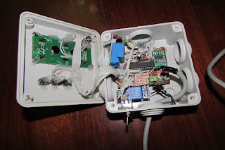
This device is built on top of an ATmega8 running @ 8Mhz. It has 3 button to setup all the parameters and an 2x16 LCD to monitor the working status. As weight sensor a HX711 board is used.

Configuration parameter are stored inside the ATmega EEPROM. Whenever the weight raise the minimum or maximum threshold an error is triggered. Use can set the number of errors system has to raise before the alert action happens. Whenever an alert is triggered, a relay is opened or closed, depending on the wiring desired for the external equipment.

User can set a few parameters inside the LCD, like:

  • Weight sensor calibration: here we can set the gain, the offset and the tare.
  • Interval between weights
  • Number of errors to wait for an alert to be triggered
  • Max and Min Weight error: thresholds for an alert to be triggered
This is just a simple device one can customize depending on personal needs.


Below the load cells used for test. On the industrial application this device has been attached to industrial cells.


Code


Notes
  • read risk disclaimer
  • excuse my bad english

Monday, January 3, 2022

Extended button debounce library

I've previously introduced my debounce library here: http://davidegironi.blogspot.com/2018/10/switch-debounce-library.html

This post is about an expansion to that library.

In brief, this library try to solve the contact bounce issue (ref. https://en.wikipedia.org/wiki/Switch#Contact_bounce), implenting the Jack Ganssle's article "A Guide to Debouncing" idea. As my previous library, this too is based upon the Trent Cleghorn work, you can find here https://github.com/tcleg/Button_Debouncer

This version of the library implements the long press and other function too, let's list it all:

  • currentpressed: check if button is currently pressed
  • pressed: check if a buttons were immediately pressed
  • pressedchange: check if a button were pressed since the last request
  • released: check if a buttons were immediately released
  • releasedchange: check if a button were released since the last request
  • continuouspressed: checks if a button were continuous pressed
  • longpressedchange: check if a button were long pressed since the last request
  • longreleasedchange: check if a button were long released since the last request

Those functions covers most of the requirements you may have handling buttons.

The buttondebouncer.h file contains all the parameters such as the constant value that defines how many step the debouncer will take to get a long pressed button state.

The library has been developed on a ATmega running @ 1Mhz, but it can easly ported to other microcontroller.


Code

Notes
  • read risk disclaimer
  • excuse my bad english