Tuesday, December 3, 2019

An ATmega brushless sensorless motor driver v02


Brushless electric motor (BLDC motors) are synchronous motors that are powered by a DC electric source via an integrated inverter/switching power supply, which produces an AC electric signal to drive the motor.
For an introduction to BLDC motors, you can take look at my sensored motor driver post, here: http://davidegironi.blogspot.it/2013/09/a-simple-brushless-sensored-motor.html or you can browse the internet, you will find there is a lot of litterature about BLDC motors.


This library implements a brushless sensorless motor dirver for AVR ATmega.
To write this library I take inspiration from the library above:

This library take inspiration from:
The code i propose is written, tested and compiled using avrgcc over an ATmega8 running at 16Mhz.
I've also tested a version of this code on ATmega8 running at 8Mhz.
The aim of is project is to build a fairly simple bldc driver one can embed and easly modify in order to meet their own needs.

There are of course driver that performs better than this one, so if you are looking for best performance and you are using an ATmega micro, i suggest you to take a look at the SimonK firmware (https://github.com/sim-/tgy) or the BLHeli firmware (https://github.com/bitdump/BLHeli).

My previos driver you can find on links above does not fully implements PWM, also the brushless sensorless version to detect Zero Crossing reads the ADC voltage insted of using the internal ADC comparer.

Like the previos driver, this one implements a speed and direction (clockwise and anti-clockwise) controller.

Speed and direction can be set using the proper function, the speed have to be set using a 0 to 100 interval. 0 will stop the motor, direction has defined macro available for CW and CCW set.

In the sample main file the speed is driven by an RC input library, binded to the external interrupt input PIN.
For the test project the RC signal generator is a servo tester.
The RC reader library can be found here: http://davidegironi.blogspot.com/2018/03/an-avr-atmega-rc-control-signal-reader.html
Settings for this library can be changed on the rcin2.h file.

The bldcsetup.h file containst the main settings. As example there you can find the RC input library enabler.

This driver implements 4 PWM schemes:
  • H PWM L ON: PWM is performed on the ON channel
  • H ON L PWW: PWM is performed on the OFF channel
  • H PWM ON: PWM is performed on UWV channels every 60degrees, starting from U ON-ON
  • H ON PWM: PWM is performed on UWV channels every 60degrees, starting from V OFF-NULL
The PWM scheme is the way the power gates bridge is controlled in order to drive the motor.
One can chose the PWM scheme in the bldcsetup.h file.

The main.c file is a sample running project that use this library to run a motor.

bldcsetupmicro.h file contains specific microcontroller definition, this file should allow the implementation of this library over others than the ATmega8 microcontroller. It contains ADC registry settings and TIMER settings.

This driver can run on many board pinout, input/output PIN can be changed in the bldcsetupboard.h file.
The adc mux schema represent the order of PIN chosen as Zero Crossing detection depending on the running step.

The commutation sequence is defined in the bldc.h file.
By default it is set as follow (first group is the U bridge switch, second is the V, third is the W):
  • Step 1: 10-01-00
  • Step 2: 10-00-01
  • Step 3: 00-10-01
  • Step 4: 01-10-00
  • Step 5: 01-00-10
  • Step 6: 00-01-10
The picture below represent the commutations:


The interface with the user consists in a bounch of function that performs:
  • initialization of the library
  • speed selection or retrive
  • direction selection or retrive
  • speed retrive in RPM
  • debug function to retrive the status of the driver

Two TIMER are implemented:
  • TIMER PWM: works as the PWM emitter, it emit the commutation to the power bridge according to the selected step
  • TIMER MAIN: select the step to emit, depending on speed and direction selection. It works in three modes:
    • startup mode: perform the startup sequence of step
    • emission mode: select the commution step to run and switch to non emission mode
    • non emission mode: check the BEMF for Zero Crossing detection, once the ZC is detected, the mission mode is triggered
Two error detection strategies are implemented, both the strategies can be enabled or disabled at compile time. ZC detection error and Max Ticks between steps detection. Both the strategies trigger a motor startup when the max number of errors is reached. The ZC detection errors makes a +1 increment whenever a ZC crossing should be detected but it was not. The Max Ticks between steps makes a +1 increment whenever a step happens.

The RPM speed estimation is performed assuming the TIMER A runs at a fixed frequency.

Further improvement can be made on the whole driver, expecially the startup stage.

Code

Notes
  • read risk disclaimer
  • excuse my bad english

Wednesday, November 6, 2019

WiiPoser: a Wii Nunchuck + led matrix + pan/tilt servo laser pointer frame

- ref 2013 -


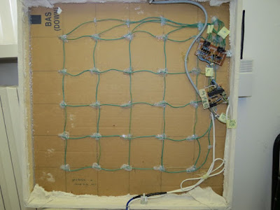
WiiPoser is Wii Nunchuck + led matrix + pan/tilt servo laser pointer frame.
I've build this frame to test the Wii Nunchuck library years ago.
Nunchuck is a wii 2-axis joystick, two buttons and a 3 axis 2g accelerometer.
You can find the nunchuck driver here: http://davidegironi.blogspot.com/2012/11/avr-atmega-wii-nunchuck-library-01.html


This is just an unsuefull frame built to test some libraries.
Behind the canvas of the frame there's a 5x5 led matrix driven through a bunch of general purpose NPN transistors.


The main controller it's an ATmega8, running @8Mhz.
There's a pan/tilt servo bracket that moves the laser pointer.


The Wii Nunchuck drives the servos pointer.
One of the Nunchuck button change the led view mode, in mode one just one led is on, in mode two just one led is off.
The second button of the Nunchuck switch the laser pointer on and off.
The Nunchuck joystick is used to select which led has to be powered on or off.


If no movment is perceived the frame goes in a demo mode, the demo mode moves the servos and switch on and off the leds in a random mode.


Code

Notes
  • read risk disclaimer
  • excuse my bad english

Saturday, October 5, 2019

Linux Mint on Z83-F Intel Atom X5-Z8350 mini PC


The Z83-F is a mini PC from Minis.

It has 4GB of memory and 64GB of flash storage, the CPU is Intel Atom X5-Z8350. Speaking of connectivity, it has a pair of USB 2.0 ports, a single USB 3.0 port, an HDMI port (with 4K support), an SD card slot, a VGA port, an Ethernet port and a headphone-microphone combo. This mini PC also inclues a dual-band 802.11a/b/g/n Wi-Fi adapter and Bluetooth 4.0 one. No fan inside, it just has a big heat sink for thermal dissipation.
Mine comes with Windows 10 Pro pre installed.
Find below the top and bottom view of the board of this mini PC.


Unluckly Windows is a big beast, the poor Atom processor is not able to give a good experience to the user. Also after a while it stucks on the Windows logo.
I would like to use this PC as a second house desktop, so the main use of this PC would be browsing and remote connections.
Using Windows, even with Chrome or Firefox the browing experience is so sad, slow and smooth page scrolling and lags on Youtube videos. For this reason I choose to try a linux installation on this PC.
The MinisForum is the place to look at, if you would like to install any other than Windows, or to solve any problem related to your Minis PC.


I choose the Linux Mint 19.1 Xfce version. Compered to Cinnamon version, Xfce uses less resources and for this reason the user experience is smoother. By the way Xfce is a lightweight desktop environment, for the purpose of this PC it's enough.
The installation procedure is simple, like any other installation at first you have to prepare the USB install drive, I've used Rufus for this.
Then at boot press the Delete button to enter the BIOS during startup, and press F7 to select the startup item.
Install Linux Mint on the main drive.
After you have installed it, at the first boot you have to fix WiFi and audio.
The audio chip of this PC is the bytcr-rt5651, WiFI is brcmfmac43455.
I've prepared two script, one for audio, and the other for WiFi. The scripts simply updates the driver for both the chip.
The audio enabler does the following actions:
sudo cp -rf bytcr-rt5651 /usr/share/alsa/ucm
sudo cp asound.state /var/lib/alsa
sudo cp blacklist_snd_hdmi_lpe_audio.conf /etc/modprobe.d/
The WiFi enabler simply move a single file:
sudo cp brcmfmac43455-sdio.txt /lib/firmware/brcm/
You can download the installation script at the following location:
https://sourceforge.net/projects/davidegironi/files/dev-install/Z83-F_linuxmint19.1_audio-video_v1.zip/download
Then you have to unzip that file, under the Z83-F_audio folder run install.sh to enable the audio chip, under the Z83-F_wifi run install.sh to enable the wifi chip. The following commands will set install.sh as executable, and run it.
sudo chmod a+x install.sh
sudo ./install.sh
Now reboot your PC, you should now have the WiFi chip enabled, as the audio chip.


With Linux Mint installed, this PC to me is now "usable" at least for browsing.
As i tell you, I'll use this PC for remote connections too, to use this capability just install the Remmina package, if you need it, install also the rdp package using the following commands:
sudo apt-get install remmina remmina-plugin-vnc remmina-plugin-rdp

Notes
  • read risk disclaimer
  • excuse my bad english

Sunday, September 1, 2019

Drive an MCP49XX series DAC with an AVR ATmega


digital-to-analog converter (DAC) is a system that converts a digital signal into an analog signal.

The MCP4901, MCP4902, MCP4911, MCP4912, MCP4921, MCP4922 are DAC converters by Microchip.
They have 1 or 2 channel output, 8, 10 or 12 bit buffered voltage output.
The interface used to drive those IC is the SPI.


Driving that IC is pretty simple, expecially if you have a dedicated SPI hardware interface, like many microchip has.
The ATmega8, used in this example has a dedicated SPI Control Register (SPSR) that one can use to setup the SPI interface.

This library can drive more then one MCP49XX of the same series at the same time, this is done just by selecting the chip using a SS channel for each one.

A few functions are available in order to set a raw value for the DAC channel, a selected voltage, to power the IC down or up, and to get the actual raw value.
On compile time you have to set ports to use, and the MCP49XX family.


The sample schematics contains also an output stage build up using a LM358 opamp with a non-inverting configuration.

In non-inverting configuration the Gain is R2/R1 + 1, given R2 the resistor between out and - input, and R1 the resistor beteen - input and GND. The sample gain of 3.2 amplifiy the input signal taken from the DAC by 3.2, of course the output voltage can not exceed the power supply voltage of the opamp. For this reason if you supply the LM358 with a 12V supply, a sample output voltage of 2.4V will became 7.68V output.

The output current is limited to 20mA for a sink load and 40mA for a source load.

By simply adding a power MOSFET you can amply the output current that can be draw.

The example is provided runs a sine wave output or a selected voltage output.

All the setup parameters are included in the mcp49xx.h file.

The library proposed here can be ported to other microcontroller without difficulties.

This library was developed on Eclipse, built with avr-gcc on Atmega8 @ 8MHz.


Code

Notes
  • read risk disclaimer
  • excuse my bad english

Thursday, August 8, 2019

My Ruby Amp Bassman mod small bass amplifier


The Ruby Amp it's a small instrument amplifier based on the LM386 IC.


Original circuit can be found in the http://www.runoffgroove.com/ruby.html page.
Basically this amplifier is composed by an N-Channel JFET input buffer that adjust the impedance of the instrument pickup. The speaker driving job it's done by the LM386.


You can find an in-depth analysis of this small amplifier in the electrosmash.com page here: https://www.electrosmash.com/ruby-amp-analysis.
The circuit I propose here it's the Ruby Amp with Bassman mod plus a Distortion mod switch.
I've removed the original amplifier circuit of a junked Creative Subwoofer from a Creative SBS 390 2.1 system, and replaced it with the one I've built.


The PCB was design in EagleCAD and printed from a chinese PCB service. The one you find here it's the revised version of the video one. The circuit is the same, I just changed a bit the layout.
I must say this amplifier sounds pretty good to my ears. It's not that loud, but it's enough to play at home.


Notes
  • read risk disclaimer
  • excuse my bad english

Monday, July 1, 2019

Use a MCP4728 DAC with AVR ATmega

Updated to version 04


The MCP4728 device is a quad channel, 12bit voltage output DAC. It also has EEPROM embedded.
The DAC is driven using the I2C interface.

This library implements an ATmega driver for this IC.


The selected I2C library is the one proposed by Peter Fleury, you can find it here: http://homepage.hispeed.ch/peterfleury/avr-software.html

This library can drive up to 8 IC, depending on the MCP4728 selected address.

Each individual channel can be powered down, then wake up.
User for setting gain, raw output value and voltage value is provided. Also values can be stored to IC EEPROM.

The reference voltage can be set as internal, that is 2.048V, or external.

The sample provided output a sine wave, or a voltage output test.

The max output voltage depends on the gain and the voltage reference selected, if external voltage is selected as reference the gain is omitted.


This project has been developed and tested on an ATmega8 running at 8Mhz.

ChangeLog
  • 04: fixed eeprom functions
  • 03: added mcp4728_setdacvdd, mcp4728_setchannelvalue methods
  • 02: first version.
Code

Notes
  • read risk disclaimer
  • excuse my bad english

Monday, June 3, 2019

AVR ATmega UV meter using ML8511


This device is a UV meter built on top of an ATmega8 microcontroller and a ML8511 UV sensor.
It measures UV light intensity and the UV index.


The ultraviolet index or UV index is an international standard measurement of the strength of sunburn-producing ultraviolet (UV) radiation at a particular place and time. It is a linear scale, with higher values representing a greater risk of sunburn. The purpose of the UV Index is to help people effectively protect themselves from UV radiation.


It features an LCD display that shows you all the measurements, a temperature sensor to correlate the output against temperature too, the UV led is attached to this meter makes this device particularly suitable to test glass UV lens. It also works with a 9V battery.
The LCD displays UV light intensity in mW/cm2, UV index, current temperatore, a light intensity offset, that this the difference from two values of UV, and the UV wavelength measured.
The light intensity offset is usefull to measure the real UV intensity reduction of a lens for example.
In my case the UV led mounted is a 3W@365nm, so I set the wavelength to 365, but one can change it using the menu that is accessible by long pressing the Select button.


For further information on the sensor library please take a look at my blog post here: http://davidegironi.blogspot.com/2018/05/uv-sensor-ml8511-avr-atmega-library.html.


Code

Notes
  • read risk disclaimer
  • excuse my bad english

Thursday, May 2, 2019

D01: 2*15W guitar amplifier built using salvaged parts

-- ref 2013 --


The D01, litterally Discarica 01, is a guitar solid state amplifier build from salvaged parts.


Speakers are from a ready-to-be-trashed TV, the wooden case is something laying around here waiting to be trashed, some of the components are taken apart from old devices, like the transformer.
Of course there's something new in this amplifier, but most of the parts comes from savaged hardware.


The preamplifier it's based on the Descrete FET Guitar Preamp by J. Donald Tillman (http://www.till.com/articles/GuitarPreamp/). It's a J201 N-channel JFET based preamp that sounds really good.
The signal goes than to a clean/dstortion selection switch.
The distortion section it's based on a modded version of the Electra Distortion Pedal, that runs with just one 2N2222 NPN transistor. The distortion section has its own volume.


The output is then routed to the main volume and then to the main amplifier board.
The amplifier board it's based on the TDA7297 2*15W dual bridge amplifier. It costs just a few euros the complete board shipped with headsink, so this time I've buy this one.


The two speakers are 4ohm, savaged from an old TV.
The power section of my built consists of a 220V to 15V transformer with a 30W output current. Because the rectified voltage was a little too high for my circuit I use a simple DC/DC stepdown LM2596 board to reduce the voltage to 9V.


I assembled all those things in a wooden case build from some recycled boards.


I must admit that this amp sounds really nice, it has a nice vintage look, and the distortion section sounds really fat to me, although of course its has not a big output.


Notes
  • read risk disclaimer
  • excuse my bad english

Thursday, April 4, 2019

HX711 load cell amplifier library for AVR ATmega

Update to v02


HX711 is a precision 24bit ADC IC designed for weigh scales and industrial control applications to interface directly with a bridge sensor.

A load cell is a transducer that is used to create an electrical signal whose magnitude is directly proportional to the force being measured.

The library you can find here is usefull to implement a weigh scale using the HX711.


References used to implement this library are
This HX711 Arduino library, https://github.com/bogde/HX711
And that other library here https://github.com/getsiddd/HX711

Methods to get raw values and unit values from the HX711 are provided.
Also you can find function to calibrate the IC.

Before using this IC you have to calibrate it against the load cell used.
The calibration task is split in 2 steps:
1) The tare raw value offset needs to be obtained, To perform this task you have to run the calibrate step 1 function without any weight on the load cell.
2) Using the tare raw value and a know weight put on the scale you can capute the scale value that is used to obtain the weighted value.
For this reason is important that the reference weight has a well know value.


Once you have obtained the scale value, you can use it to get weight, and you can also perform a new tare without having to calibrate the scale again.

The sample provieded contains all the step needed to calibrate the sensor and obtain raw and unit values.

This library was developed on Eclipse, built with avr-gcc on Atmega8 @ 1Mhz.


Changelog
  • v02: fixed a bug in read function, clean code
  • v01: first version

Code

Notes
  • read risk disclaimer
  • excuse my bad english

Saturday, March 2, 2019

Guitar pickup wax potting


I've a telecaster copy by Tradition Guitars, it's a tobacco sunburst from 2005 and it sounds pretty good for the price.


Times ago i shift the default ceramic pickup with a set of Alnico 5 Vintage Plus TRT1 by ToneRider. Those pickups sounds very very good! Indeed, I want to mount those pickup on another Telecaster model I've, but I do not want to leave the Tradition TL without Alnico, so, I've buy a set of FLEOR Vintage Alnico 5 pickups from China for less than 20Eur with shipping.
The set it's composed of course by a neck and a bridge pickup for Tele syle guitar, they are wax potted, magnets are Alnico 5, and the resistance almost fits the specification, namely neck is 6k7 and bridge is 6k3.


I was skeptical about those pickups, the delivery was really fast just 2 weeks, when mounted I have to change my mind. The Fleor set sounds as vintage as the TonerRider, the bridge one it's a little bassy sounding in contrat to the ToneRider, but overall they have really a good "feeling".
BUT, there's a BUT here, cause we are speaking about guitar pickup potting on this post, the bridge one was microphonic, as soon as I plug the overdrive on it starts hissing.
I've read comments from other buyer of Fleor, no one has microphonic issues, so I think mine was just an oversight.
To me this is the opportunity to learn how to pot a pickup, in fact so i did, and with the wax potting I've solved all the issues.
I decide to disassemble this pickup and pot it.
Guitar pickup potting is a process whereby the pickup coil are encaplusated in a substance that inhibits the coil movement that may cause oscillations and so hissing. Many new pickups are potting using epoxy glue, but old and vintage pickups use wax.
When I remove the tape around the coils of the bridge pickup I've notice that it was potted, but the wax does not soaks coils under the tape, it seems to me that the employee that pot this pickup forgot to leave this enough time in wax or do pot with the tape on it.

Warning! Paraffin is flammable and fumes may be toxics. Do pot in open environment. Potting is made at high temperature, pay attention to your skin. Everything you do at your own risk.

Here is the recipe I've used:
  1. 80% paraffin + 20% beewax
  2. put this mixture in a pot, then the pot in waterbath till the wax liquefy
  3. check the temperature, it should be something around 60degree
  4. put the pickup in wax, try to prevent the pickup to touch the pot
  5. leave the pickup there for almost 20 minutes
  6. take the pickup out and clean with a rag, then wait till it cools down
While potting you should see small air bubbles that cames out from the pickup, that's normal it's the air between coils that leaves the space to the wax.
I've pot both the pickup, just in case.


Reassembling the bridge pickup I've put the tape back, then wrap a cord on the pickup just to give it a vintage look.
To my surprise when i mount the pickups back, they both still works, and microphonics issue was gone!
This is how I potted the pickup, of course I'm not an expert on this field, so if you have suggestions or tricks put comments below.

Notes
  • read risk disclaimer
  • excuse my bad english

Monday, February 4, 2019

Bad Ragaz Fuzz - Germanium Fuzz pedal


Here i present a Germanium Fuzz Pedal I've recently build.

It happens that a friend of mine was about to throw away a late 60's record player. This record player was in his old house, the case of the player get wet and unusable due to a loss in the ceiling. This friend also throw away a steel boxfrom ELESTA AG, the plate reads: Bad Ragaz, which sounds like Bad Boy in a mix of italian and english.


I have disassemble it and take all the components out, to my surprise it contains a bounch of germanium transistors. So i decide to build this pedal.

The pedal design is simple, I just stared from the Vox ToneBlender original schematics, which is a Fuzz i really like, and change some values to match the sounds i like more with the components I have.


I've used two PNP germanium transistor: the SFT337, and the AC142. Then I changed the original ToneBlender fixed collector resistor with a Bias potentiometer, that define the Badness of the sound, because we are talking about a Bad Ragaz.


As a side note I must admin that altough germanium transistor sounds goods, they are slighly more difficult that to drive, as example microphonics noise can happens, and noise more in general it's around the corner.

Find below the schematics.


And the original Vox ToneBender


Notes
  • read risk disclaimer
  • excuse my bad english

Tuesday, January 1, 2019

Use a MCP23017 GPIO port expander with an ATmega


The MCP23017 is a general purpose I/O port expander, it is driven using the I2C interface.
Each of the 16 channels can be set independently as an input or as an output pin.

This library provides functions to drive up to 8 MCP23017, it means you can expand your micro to 128 between input and output.


One of the interesting feature of this IC is the possibility to set an interrupt.
Interrupts can trigger a change on both INTA and INTB chip output, if mirror mode is selected a change on the bus A, or B trigger interrupts on both INTA and INTB.
One can also set the polarity of the interrupt, it means if the input gives you a high or low level on output.
Output interrupt channel can also be set as open drain.
You can set interrupt on each individual input channel, setting the compare mode, i.e. if the pin status has changed since the last reading, or if the pin has changed compared to a value set by the user. This last option is usefull if you want as example to set the comparation for rising or falling mode.
Then the interrupt can of course be enabled just for a single pin.

This interrupt features gives you the ability to quickly detect the change on a pin.

This library also provides function to set each individual pin mode as input or output, output pin status and read input pin status. Functions to read group of values for the full A or B channels as byte are also provided.


This library was developed on Eclipse, built with avr-gcc on Atmega8 @ 1MHz.

If you want further information on that IC, i suggest you to take a look to that two interesting articles on that IC:

ChangeLog
  • 01c: fixed main sample project
  • 01b: fixed an error on addressing when multiple IC connected
  • 01: first version

Code

Notes
  • read risk disclaimer
  • excuse my bad english