The Honeywell HMC5883L is a surface-mount, multi-chip module designed for low-field magnetic sensing with a digital interface for applications such as lowcost compassing and magnetometry.
This library implements a way to get values from hmc5883l.
If your magnetometer stands with z-axis parallel to ground, you can get y and x raw values from magnetometer, and trasform it degrees using this formula:
heading = atan2(y_raw, x_raw) * 57.29578;
Then you should add magnetic declination (in degrees) for your location, to get yours visit http://magnetic-declination.com, if you have an EAST declination use +, if you have a WEST declination use -.
Then add this value to your heading.
Calibration is suggested to get more accurate parameters.
Setup parameters are stored in file hmc5883l.h
This library was developed on Eclipse, built with avr-gcc on Atmega8 @ 1MHz.
If you include math.h add libm library to linker.
The L3G4200D is a low-power three-axis angular rate sensor able to provide unprecedented stablility of zero rate level and sensitivity over temperature and time.
This library implements a way to get values from l3g4200d.
Calibration is suggested to get more accurate parameters.
Setup parameters are stored in file l3g4200d.h
This library was developed on Eclipse, built with avr-gcc on Atmega8 @ 1MHz.
A magnetometer is a measuring instrument used to measure the strength and, in some cases, the direction of magnetic fields.
A compass is a navigational instrument that measures directions in a frame of reference that is stationary relative to the surface of the earth.
We can use magnetometer to build a compass.
Magnetic distortions can be categorized as two types—hard iron and soft iron effects. Hard iron distortions arise from permanent magnets and magnetized iron or steel on the compass platform. These distortions will remain constant and in a fixed location relative to the compass for all heading orientations. Hard iron effects add a constant magnitude field component along each axes of the sensor output. The soft iron distortion arises from the interaction of the earth’s magnetic field and any magnetically soft material surrounding the compass.
This Python script implements a simple Magnetometer calibration routine to estimate soft and hard iron correction values.
The bias obtained will correct hard iron errors, the scale factor will correct soft iron errors.
To obtain values, run this python script and follow the instructions.
A processing script is also provided to collect raw values.
Once you obtain those values you can get calibrated data by applying this formula: xt_raw = x_raw - offsetx;
yt_raw = y_raw - offsety;
zt_raw = z_raw - offsetz;
x_calibrated = scalefactor_x[1] * xt_raw + scalefactor_x[2] * yt_raw + scalefactor_x[3] * zt_raw;
y_calibrated = scalefactor_y[1] * xt_raw + scalefactor_y[2] * yt_raw + scalefactor_y[3] * zt_raw;
z_calibrated = scalefactor_z[1] * xt_raw + scalefactor_z[2] * yt_raw + scalefactor_z[3] * zt_raw;
Once you obtain raw values using the script provided, to compute offset and
scale factor values, you can use the matlab script or magneto12 program provided.
On the microcontroller side you have to setup a function that print out to UART
raw values read from your chip.
Given 2 bytes (int16_t) variables for every axis, output the LSB and then MSB
byte ((uint8_t)(int16_t>>0) + (uint8_t)(int16_t>>8)), follow by a '\n' char.
Snippets are provided for AVR Atmega and Arduino, but it can be setup for other micro too.
A gyroscope is a device for measuring or maintaining orientation, based on the principles of angular momentum.
Almost every gyroscope chip has to be calibrated, because every device brings a manufacturing error.
In case of gyroscope the correction parameters we need are gain and offset.
Once you obtain those values you can get calibrated data by applying this formula: x_calibrated = (x_raw-offsetx) / gainx
y_calibrated = (y_raw-offsety) / gainy
z_calibrated = (z_raw-offsetz) / gainz
This Python script implements a simple Gyroscope calibration routine to estimate offset and gain calibration values.
To calibrate offset we just leave gyroscope in a stable position.
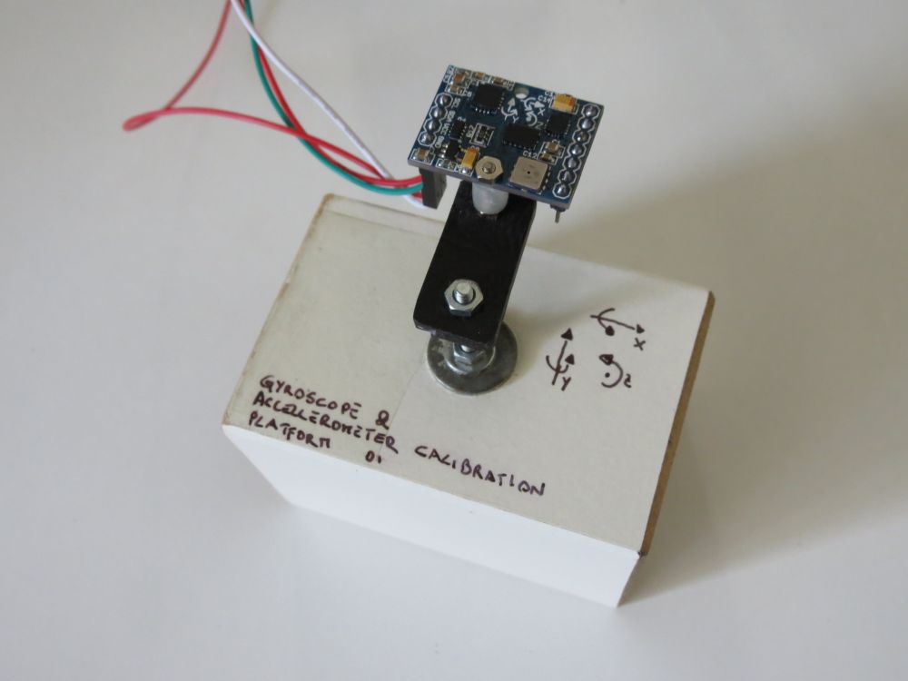
To correct gain, this script do not use a calibrated rotation platform. I use an integration method. User must rotate it in 6 differenct way (see sheet provided) for a fixed angle, i use 90 degrees, cause i can do it with a simple calibration platiform (a cube), but greater angles (3600) would bring to better calibration.
The rotation plane of the gyroscope have to be parallel to the requested rotation, so try to be precise placing the sensor over a rotation platform, and rotating it.
During every rotation the script collect raw values. Integrating those values gives use the raw total values for the angle formed. Because we fixed the angle we should estimate the gain factor for the raw values. I sense the rotation stop evaluating raw values, a better way should be adding stop sensors. I suggest to repeat calibration more than one time, cause small rotation error can lead to calibration error.
To obtain values, run this script and follow the instructions, a calibration sheet is provived to help you directing the sensor.
If you run your sensor in a big range of temperature you should also consider a calibration dependent to temperature too.
You can run the script function that compute temperature compensation values.
Cool down you chip, then launch the script, while the sensor come back to ambient temperature, this script collect values, then compute linear regression to find suitable temperature compensation values.
Now, given a tempdelta, that is a temperature delta difference from the sensor start time
tempdelta = actualtemp - starttimetemp
The calibrated axis would became: x_calibrated = (x_raw-((tempcompx*tempdelta) + offsetx)) / gainx y_calibrated = (y_raw-((tempcompy*tempdelta) + offsety)) / gainy z_calibrated = (z_raw-((tempcompz*tempdelta) + offsetz)) / gainz
You may repeat those tests a few times to get better results.
On the microcontroller side you have to setup a function that print out to UART raw values read from your chip.
Given 2 bytes (int16_t) variables for every axis, output the LSB and then MSB byte ((uint8_t)(int16_t>>0) + (uint8_t)(int16_t>>8)), follow by a '\n' char .
Snippets are provided for AVR Atmega and Arduino, but it can be setup for other micro too.
Changelog
02: small fix on the gyro_docalibration.txt readme file for the tempcomp function for x_calibrated, y_calibrated, z_calibrated
An accelerometer is a device that measures proper acceleration.
Almost every accelerometer chip has to be calibrated, because every device brings a manufacturing error.
In case of accelerometer the correction parameters we need are gain and offset.
Once you obtain those values you can get calibrated data by applying this formula: x_calibrated = (x_raw-offsetx) / gainx
y_calibrated = (y_raw-offsety) / gainy
z_calibrated = (z_raw-offsetz) / gainz
This Python script implements a simple Accelerometer calibration routine to estimate offset and gain calibration values.
To calibrate the accelerometer user have to place it in 6 different position (see sheet provided). The collected values are then computed to correct gain and offset.
offsetx = (x_raw_at_+1g + x_raw_at_-1g) / 2
offsety = (y_raw_at_+1g + y_raw_at_-1g) / 2
offsetz = (z_raw_at_+1g + z_raw_at_-1g) / 2
gainx = (x_raw_at_+1g - x_raw_at_-1g) / 2
gainy = (y_raw_at_+1g - y_raw_at_-1g) / 2
gainz = (z_raw_at_+1g - z_raw_at_-1g) / 2
If you run your sensor in a big range of temperature you should also consider a calibration dependent to temperature too.
To calibrate your sensor you should collect values in a stable position, collecting temperature also.
You should find that the temperature against raw values is more or less linear, so you can estimate a temp_coeficient values, and your formula could became like this:
z_calibrated = (v_raw - offsetv - temp * temp_coeficient) / gainv;
To obtain values, run this script and follow the instructions, a calibration sheet is provived to help you directing the sensor.
On the microcontroller side you have to setup a function that print out to UART raw values read from your chip.
Given 2 bytes (int16_t) variables for every axis, output the LSB and then MSB byte ((uint8_t)(int16_t>>0) + (uint8_t)(int16_t>>8)), follow by a '\n' char.
Snippets are provided for AVR Atmega and Arduino, but it can be setup for other micro too.
This is a simple Python script to fetch one COSM / pachube datastream.
Cosm is a secure platform for Internet of Things devices and products. Its API and web service provide real-time control and data storage.
Unfortunately on these days cosm.com does not provide any software to download a datastream data, so i've build this script, which use cosm api to download datapoints of a datastream.
Before launch the script, you have to open the script with an editor and setup some parameters.
#setup your cosm account data here
#set cosm key
COSM_APIKEY="YOUR_COSM_APIKEY_HERE"
#set cosm feed id
COSM_FEEDID=YOUR_FEED_ID_HERE
#set cosm datastream
COSM_DATASTREAM=YOUR_DATASTREAM_HERE
#download datastream backward from DATETO to DATEFROM, with datapoint interval of INTERVAL (seconds), and backward step of DATEINTERVAL (hour)
#cosm history interval request
INTERVAL=0
#get backward from DATETO to DATEFROM
DATEFROM=datetime(2012,12,5,15,45,0)
DATETO=datetime(2012,12,8,15,45,0)
#interval between requested data (in hour)
DATEINTERVAL=1
#output file name, and conversion (date) to csv format
#set output file
OUTFILE="out.csv"
#convert cosm data
CONVERTDATA=1