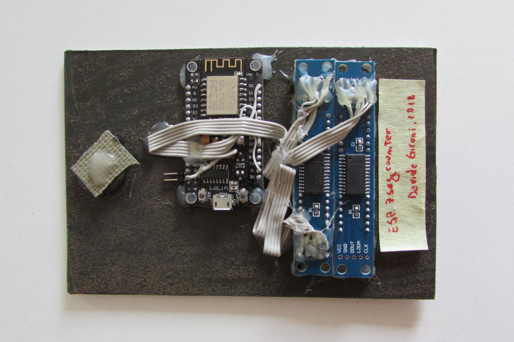
In this post here I would like to share with you a double line 8 digits seven segment PCB board. Ready to be printed and builded.
Also, I attache here the CAD files that you can use to print you own box for this counter.
The board was built using Eagle.
The seven segments module that i use are the HS420361K-32, which is a common cathode module with the following wiring.
pin 01: E pin 02: D pin 03: dp pin 04: C pin 05: G pin 06: dig4 pin 07: B pin 08: dig3 pin 09: dig2 pin 10: F pin 11: A pin 12 dig1
Please find the connection diagram below. Of course the wiring of 4 bit seven segment modules changes by the model you use, so pay attention to your wiring scheme.
The box was designed using Autodesk Fusion 360 and printed using a Creality3D Ender-3 Pro on PLA.
The ESP8266 seven segment counter is a WiFi enabled device that updates one ore more 7 segment led display by loading data from a RESTful API.
The device is based on a ESP8266 chip. It uses the WiFiManager (https://github.com/tzapu/WiFiManager) library to simplify the settings of the AP the board has to connect to. If the ESP8266 can not find the last network used, or no network is set, the ESP8266 enters the "forced AP mode", now the user can connect to the device WiFi and set the main WiFi AP to be used for the internet connection.
When it's connected WiFi AP the IP address given by the main AP DHCP server, or the static IP of the device is shown on the first seven segment dispaly.
The user can change the API uri used to get the data, and the interval of the data routine from the settings web page.
Whenever the interval time, which is by the way expressed in seconds, is passed by, the ESP8266 performs a GET requests on the API uri, then try to parse the results. The result must be plain text format: each line must be a numeric value that will be shown on the display. Of course it's just a matter of changing a little bit of code to customize the parsing function to fit the desidered API uri.
If errors happened, nothing is display till a threshold number is reached, then the last error is displayed.
The schematics and the board for this project is as simple as the code.
The power comes from the 5V port, a mini USB is used, then a linear regulator reduce the voltage to 3.3V used by the ESP8266 board, that is a ESP-12F pinout compatibile one.
The seven segment display driver is the MAX7219.
Even the numer of 8 bit seven segment display is pretty simple to customize by changing a few lines of code.
The one proposed here has 2 seven segment 8 digits display, one display for each driver, but with just a few changes it will be easy to add or reduce the number of digits to use.
ESP/Temperature To ThingSpeak is a smart temperature meter that sends temperature to the ThingSpeak service.
It's based on the ESP8266 board and uses the ADS1115 analog to digital converter in order to read the resistance value of up to 4 NTC sensors and convert it to the temperature value. The NTC to temperature convertion is performed using the library you can find here http://davidegironi.blogspot.com/2018/01/esp8266arduino-ntc-library.html
The code is written using the Arduino ESP8266 framework.
The WiFiManager library it is used to simplify the settings of the AP the board has to connect to. If the ESP8266 can not find the last network used, or no network is set, the ESP8266 enters the "forced AP mode", now the user can connect to the device WiFi and set the main WiFi AP to be used for the internet connection.
When it's connected WiFi AP the IP address given by the main AP DHCP server, the default web page is accesible at the ip address of the device or at the address http://esptemperaturetothingspeak001
Through the web interface one can also set the unit of temperature and the ThingSpeak API Key and Channel ID.
A ThingSpeak channel has to be setup, it must have 1 to 4 Fields, depending on the NTC sensor added. Then the Write API Key and the Channel ID should be filled up in the web interface of this mini device in order to allow the temperature to be sent to ThingSpeak.
Each seconds the device read the raw value from the ADC, convert itt to resistance, and then use the resistance value to get the temperature.
Each minute temperatures where sent to ThingSpeak.
The code is really simple and can be modified according to your needs. Just download it, compile and use it.
The gear introduced here is a device that use a ESP8266 to print text that comes from a RESTful API or from an internal database to an ESC/POS thermal printer.
ESC/P (Epson Standard Code for Printers) is a printer control language developed by Epson to control computer printers. The ESC/POS is a variant for controlling receipt printers as commonly used at the point of sale (POS).
The clue here is to build a device that call a RESTful API, and print the text the API returns to a thermal printer, and eventually fits a thermal printer.
I want the printer to be capable of printing:
when a button is pressed
once in a day at a specific day time
many times after minutes have passed
To build this thing I decided to use a ESP8266.
At startup the ESP8266 try to connect to a WiFi network, if it does not reach the last network used, or no network was imposed before, the device comes to a "forced AP mode", that way one can connect to the device WiFi and set the main WiFi AP to be used for the internet connection. The WiFiManager (https://github.com/tzapu/WiFiManager) library it's used for this purpose.
Whenever the IP address is released at the device by the DHCP of the main AP, or even if a static address is imposed, the device address is printed on the thermal printer.
This address is useful to access the settings page.
All the settings for this device are accessible by the web page embedded in it, like custom header, footer, ESC/POS commands, cut paper and print logo enabler, day/time printing period, the text database and other.
If the device is connected to the internet, and the RESTful API uri is inserted, then the device call the API and print out the text returned, otherwise a random string is selected from an internal text database.
There's also a pretty pulsing light output can be connected to a led strip to make the device look more attractive.
The board is quite simple, it features a fixed voltage DC-DC Step Down regulator, the ESP8266 in the ESP-12 package, the strip led power stage, and a voltage converter that can be populated if the printer UART voltage is not the same of the ESP8266 UART voltage (3.3v).
I've build the first gear using a prototype board, it's the one you find in the video and pictures above, but also I've embedded the PCB board in a few printer I gifted to friends.
This project is a Smart Wind Speed Meter that uses the ESP8266 to read value from a sensor, then posts results to ThingSpeak.
ThingSpeak in an application to store data from IoT devices. We are going to use the https://thingspeak.com/ website. Once we have created our account and we need to make a new channel, and collect the Channel ID and the Write API Key for that channel, we will then set those parameters in our meter configuration.
The sensor I'm going to use is a DNA701 from LSIhttp://www.lsi-lastem.it/. It's a wind speed sensor supplied with 24V AC, and industrial current output 4..20mA. A friend give this away to me, and so I would like to use in some way.
LSI sends me the datasheet for this sensor, it turned out that current to wind speed m/s is a linear function, so simple.
So, I just have to measure current with my ESP8266. In order to have an accurate measurement i prefer to use a linear current to voltage converter, then read the voltage using an ADC.
As for the current to voltage converter I go for a cheap board, it is supplied with 12V DC, and it gives you 0 to 5V output depending on the 4 to 20mA input.
Then, i read the voltage output from this sensor using an ADS1115 ADC board.
I supply the ADS1115 with 5V.
Software side I'm using the Adafruit ADS1X15 library. I initialize the sensor setting the gain to 2/3. By datasheet setting the 2/3 gain means the sensor can read +/-6.144V in 16bit. This means 6.144V in 15bit, which is 187.5uV per bit. So if we get a raw value of 32768 from the ADC, the voltage we are reading is 32768*187.5uV, which is 5V.
I prefer to add a Exponential Moving Average filter to the ADC raw value that I read, this can smooth wrong readings if there are any.
Now that we know how to read the voltage, we just have to transform back to current, that's a simple linear interpolation. For this we can use the map function.
Now that we get the current we just substitute this in the LSI conversion formula, and we so have wind speed expressed m/s.
To be more usable I've add an 8 digit seven segment display which displays the wind speed in real/time, updated each second. To be honest a 4 digit display could be enough but the simplest thing is to connect a 8 digit board you simply buy.
Then, every 60 seconds, the wind speed is sent to out ThingSpeak channel.
As on other device based on ESP8266 I've built, the WiFi AP to use can be setup using the WiFiManager integrated library. This time the device tries to connect to the AP, if any was configured, if it's not able to connect to the AP you have 3 minutes to connect to the "forced AP" of the ESP8266 and configure a WiFi, otherwise it will go on and work just like a meter with the seven segment display.
Other parameters, like the ThingSpeak Channel ID and Write API Key, can be changed in the configuration web page generated from the device itselft.
The 74HC4051 is a high-speed Si-gate CMOS device and is pin compatible with Low-power Schottky TTL (LSTTL).
The 74HC4051 IC can be used to expand the single ADC input port of the ESP8266, to 8 ports.
The ESP8266 comes with a 10bit ADC, 0 to 1V, the datasheet doesn't tell much more than this about the internal analog converter.
The output pin of the 74HC4051 is controller by 3 pins, by setting those pins high or low an analog input of the 74HC4051 is selected.
It can be driven by the same 3.3V that powers up the ESP8266.
This library was developed on Atom+PlatformIO, compiled esp8266/Arduino.
A thermistor is a type of negative coefficient resistor whose resistance is dependent on temperature, more so than in standard resistors. The resistance of a NTC Negative Temperature Coefficient thermistor (https://en.wikipedia.org/wiki/Thermistor) decreases as temperature rises. The Steinhart-Hart Thermistor Equation or the Beta Model Equation can be used to correlate the thermistor resistance to temperature to which the sensor is exposed.
The library implements the Steinhart-Hart Thermistor Equation or the Beta Model Equation to convert adc value read from analog input to temperature.
It output temperatures in Celsius or Fahrenheit.
The ESP8266 comes with a 10bit ADC, 0 to 1V, one can use the ESP8266 ADC for this library.
Suppose you are going to the internal ADC, and that NTC is going to be used between -20 and +100 degree Celsius. The NTC resistance by datasheet at -20 degree is 100k, and at 100 degree 100. To evaluate the pullup resistor you have to consider that the Voltage output at the ADC pin will be Vout = Vpullup*(Rntc/Rntc+Rpullup)
We have to consider the max Vout, that comes from the max resistance given by the NTC Voutmax = Vpullup*Rntcmax/(Rntcmax+Rpullup)
We have to chose a Rpullup such that Voutmax < 1V, so: Rpullup = Vpullup*Rntcmax/Voutmax - Rntcmax
Subsitute with the sample NTC we are considering:
Rpullup = 3.3*100000/1 - 100000 = 230000.
A 220k resistor would do the job.
In the example i propose here I am using a ADS1015 12 bit analog to digital comparator, that is much more accurate than the internal ESP8266 ADC.
I am using the Adafruit ADS1X15 library for this IC, on top of that library I've build an helper to just convert the ADC raw value that comes from the ADS1x15 to a resistance or voltage value.
Once we've acquired the NTC resistance we can use the Steinhart-Hart Thermistor Equation or the Beta Model Equation to convert the resistance value to temperature.
A digital iir filter is implemented to remove unwanted reading errors.
This library was developed on Atom+PlatformIO, compiled esp8266/Arduino.
Duck DNS (https://www.duckdns.org/) is a free Dynamic DNS (DDNS) service.
It as a few client available for many operating system and a few routers.
A friend of mine runs a router that does not support any of the Duck DNS update mode. Instead of loading his operating system with the Duck DNS updater, or installing an openwrt router, I've implemented an ESP8266 client.
It is powered by USB, it can also be powered by the router USB port.
It's built on a pretty old ESP-01 board.
It has two led, one is the ESP-01 WiFi connection status embedded one, the other is connected to the GPIO2 port, and it's used for the DNS update status.
We need just a 3.3 voltage regulator to run this board using any 5V USB power output capable of 200mA.
The code is written using the Arduino IDE + ESP8266 core, to me that's the fastest and simple way to work with ESP8266.
Also it runs a web server that allow any user to setup the DuckDNS connection parameters.
User can set the DDNS domain name and token, and also the update interval and the module hostname, that way one can just forget the module IP and open the web configuration page by board name. The default board name is espduckdns001, so the web page address is http://espduckdns001