InEquilibrio01 is a compact self-balancing robot that maintains its upright position using a PID control loop.
It is built around an ATmega328 microcontroller running at 8 MHz using its internal oscillator, and uses two inexpensive DC gear motors for actuation. An MPU6050 sensor, which integrates a 3-axis gyroscope and accelerometer, provides real-time feedback on the robot’s orientation.
A lightweight PID library enables real-time tuning of control parameters, allowing the robot to adjust its posture dynamically. PID coefficients can be programmed via PC using a bluetooth adapter (such as the HC-05) and a simple host-side library.
Although the motors are quite basic and relatively slow, making smooth balancing a challenge, the system performs reliably and demonstrates the core principles effectively.
Power is supplied by a 7.4 V LiPo battery, regulated by a DC-DC buck converter that steps the voltage down to 5 V for the microcontroller and electronics.
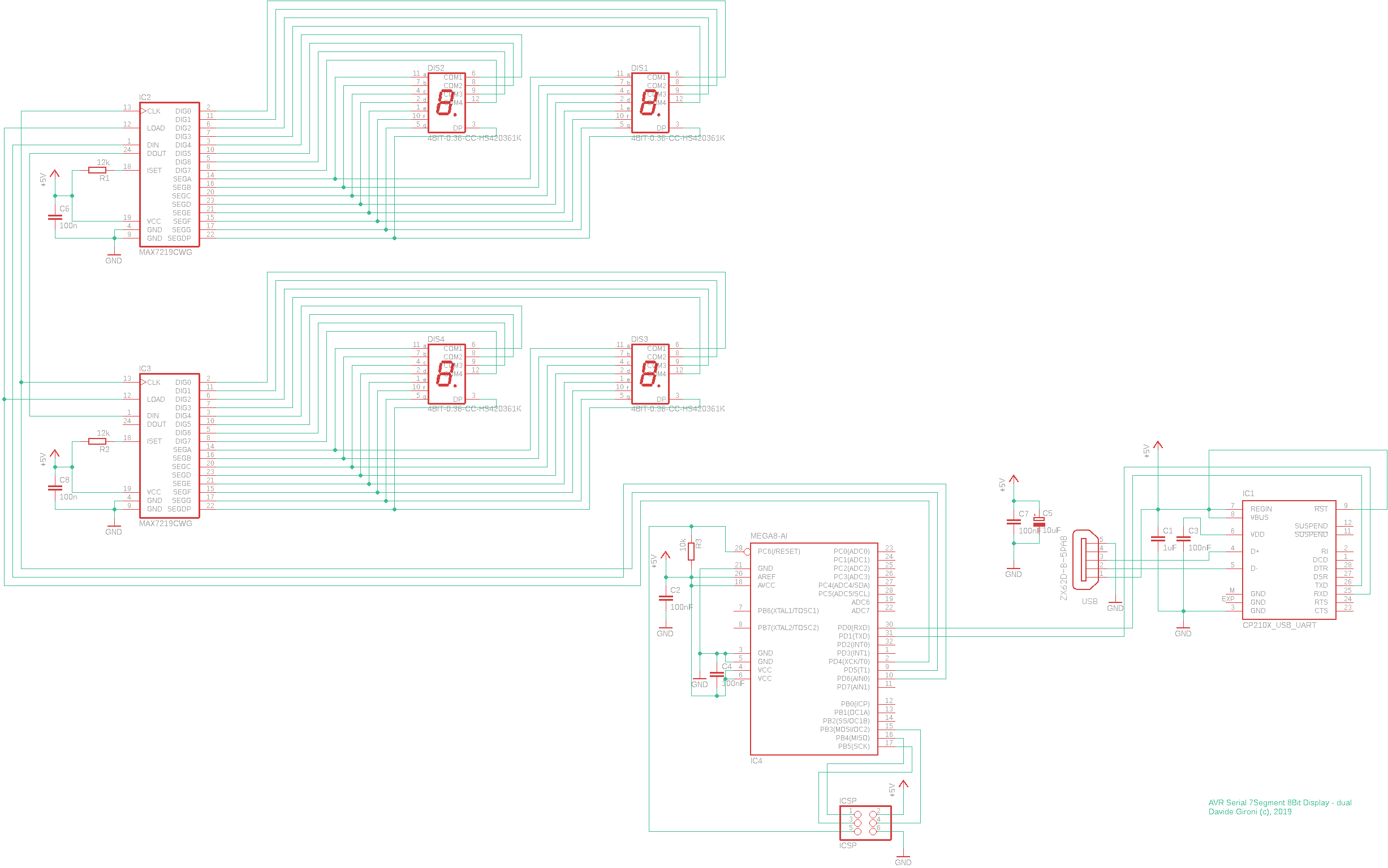
The avr_serial7segment8bitdisplay is an ATmega8 based device that get's 8 digits numbers from the UART line and display to a seven segment display with 8 digits.
As example, it can be used as exchange rate display.
By default it can display positive (max 8 digits) and negative (max 9 digits) integer and double precision numbers.
The display driver used for the seven segment display is the MAX7219.
It can perform pad left of pad right justification.
Also it can load the last values recorded to the internal EEPROM.
The protocol used to send data to the device is simple, find below the format: STX CRC dd n ETX
STX is 0x02
CRC 1 byte check code
dd (2 char numbers) is the display number 00..99
n (1 to 8 char numbers + optional . or first character minus) is the float digit, one dot, negative char and numbers allowed
ETX is 0x03
As you may notice it can handle up to 99 8 digits seven segment display.
A CRC 1 byte code is required to be sure that the data is received with success.
If the CRC code is checked successfully then the number is parsed, and eventually displayed and recorded in the internal EEPROM.
Errors in getting data can be skipped or displayed by setting the desired behavior at compile time.
A PowerShell script (https://en.wikipedia.org/wiki/PowerShell) has been used to test this device. You can use this script to write your own or to send directly your data.
The sample board provided use 2 seven segment display.
The UART to USB interface chip is the CP2102. I've select this chip cause it works without problem over the main operating systems.
The power as the data are provided through a micro USB port.
The ATmega8 runs @1Mhz using the internal LC oscillator.
I've also design a small 3D printable enclosure that I've printed using PLA.
MiniProto is a mini protocol for data exchange between devices.
It is build and tested over the serial communication protocol, but it can be ported to others.
It is designed to send strings and byte arrays.
MiniProto in the current implementation you can send up to 999 commands, and 999 byte long byte array.
The command structure is the following: STX|ACK|NAK CMD LENGTH DATA CRC ETX
Command parts are:
STX (hex 0x02): command begin
ACK (hex 0x06): acknowledgment command begin
NAK (hex: 0x15): negative acknowledgment command begin
CMD: 3 byte, ascii number, command number
LENGTH: 3 byte, ascii number, length of data
DATA: byte array
CRC: 1 byte CRC code
ETX (hex 0x03): command end
Send command can request an acknowledgment to be sent back. The acknowledgment command must contain the command number, and must start with ACK or NAK byte.
The ESC special char (hex: 0x1B) is used as escape character. Indeed if a ETX byte is sent in DATA, it is preceded by the ESC character. The escape character reduce the max length of DATA. An alternative strategy to prevent the use of the ESC character is to use the LENGTH field to read data, instead of using a read to ETX character. This may be implemented in a future version of this protocol.
Each command must have a CRC hex byte, this prevents communications errors.
CRC function is CRC polynomial x^8 + x^7 + x^2 +1 implemented using a lookup table to speed up the computation process.
DATA max length, and protocol timing can be personalized in the header file of the protocol.
Errors in communications may happens, due to timing or interference. However I'm using this protocol with decent results.
On the embedded side, there are two ways this protocol process input data.
A "blocking" one, and a "timed" one.
In the blocking way, the called functions try to read input from the selected channel, that is UART in this example. If a char is read, then the next one is processed, till the the end of protocol command, or till the threshold time passed.
In the timed way, two function are involved, one that read characters, and another that can be called to get the last command found. Most of the works is done inside the read/input function. This function read one, or up to a threshold bytes until the end of protocol command.
On both function a few other error preventing mechanism are implemented.
The timed functions most of the time it's the way to go, cause it does not stop the working loop that much. One can even put this function in a TIMER, and use the read last command function in the program loop.
I've tested this protocol on AVR ATmega8 running @8Mhz.
A NET C# client library is implemented for test.
This weight checker is device that constantly check the weight under test and possibly trigger an alert action. The alert is triggered in the form a relay.
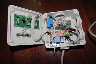
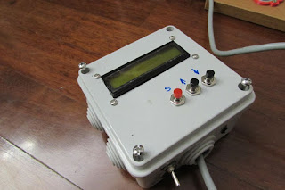
This device is built on top of an ATmega8 running @ 8Mhz. It has 3 button to setup all the parameters and an 2x16 LCD to monitor the working status. As weight sensor a HX711 board is used.
Configuration parameter are stored inside the ATmega EEPROM. Whenever the weight raise the minimum or maximum threshold an error is triggered. Use can set the number of errors system has to raise before the alert action happens. Whenever an alert is triggered, a relay is opened or closed, depending on the wiring desired for the external equipment.
User can set a few parameters inside the LCD, like:
Weight sensor calibration: here we can set the gain, the offset and the tare.
Interval between weights
Number of errors to wait for an alert to be triggered
Max and Min Weight error: thresholds for an alert to be triggered
This is just a simple device one can customize depending on personal needs.
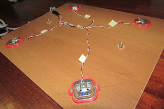
Below the load cells used for test. On the industrial application this device has been attached to industrial cells.
This version of the library implements the long press and other function too, let's list it all:
currentpressed: check if button is currently pressed
pressed: check if a buttons were immediately pressed
pressedchange: check if a button were pressed since the last request
released: check if a buttons were immediately released
releasedchange: check if a button were released since the last request
continuouspressed: checks if a button were continuous pressed
longpressedchange: check if a button were long pressed since the last request
longreleasedchange: check if a button were long released since the last request
Those functions covers most of the requirements you may have handling buttons.
The buttondebouncer.h file contains all the parameters such as the constant value that defines how many step the debouncer will take to get a long pressed button state.
The library has been developed on a ATmega running @ 1Mhz, but it can easly ported to other microcontroller.
The + is an H-Bridge driver IC that can drive up to 2 motors.
This IC as a maximum power supply voltage of 15V, with an output current of 1.2A average and 3.2A peak.
It's pretty simple to drive this chip. For each motor it has 3 input, 2 digital ones used to select the direction, the other is the PWM input.
Find below the control table for this IC, IN1 and IN2 are the two digital input that defines the direction and in conjuction with the PWM one, the Mode of operation of the OUT1 and OUT2 pin, that are connected to the motor.
It use the PWM output pins of the microcontroller, it means that no software resources are used to generate the PWM needed to drive the motors in speed.
This driver is built to control one IC, it means 2 motors independently in speed and direction.
This library was developed on Eclipse, built with avr-gcc on Atmega8 @ 8MHz but can easly be ported to other microcontroller.
All the parameters can be changed in the dcmotortb6612.h.
The drive can even run on a single motor output, we just need to change the macro DCMOTORTB6612_SINGLEMOTOR.
The board max input voltage is 45V, that is the maximum supply voltage of step-down voltage regulator LM2596-12V.
This step-down regulator provides the power voltage for the IR2101 high and low side attached to the main power mosfets of the bridge motor driver. In this design i use IRF640 mosfets, but one can also use other kind of mosfets.
A 5V regulator provides the supply voltage of the main microcontroller.
The board works both for sensored and sensorless motors.
For sensorless motor EMF signal is catched by the voltage divider network attached to pin PD6, PC0, PC1 and PC2. The PD6 pin is used in the voltage comparer configuration.
For sensorled motors digital hall sensor inputs are read by the PB0, PB1 abd PB2 pins.
A 16Mhz crystal is attached to the main ATmega8 micro, even if I've tested this board and the driver at 8Mhz using the internal ATmega oscillator circuit.
A direction switch is used to select the spinning direction of the motor.
The UART RXD and TXD pins can be used for debug or driving purpose, as example one can easly implement a protocol that control the motor driver.
Least but not last, the RC Input pin can be used to read the input of a RC servo signal.
Here you can find a sample speed test I've run over a Brushless motor Mistery D2025-5000.
To test the speed I've used a cheap Laser Tachometer DT-2234C+.
I've put tape around the motor and mark just one side of the motor tape with a black marker.
Results are pretty good, the motor spins at almost 11000rpm running at 12V, with a current consumption of 0.9A.
Don't forget that this driver is not made for performance, this driver was built to be fairly simple and easly modify in order to be easly embedded in any project. If you are looking at performance, you should take a look at the SimonK firmware (https://github.com/sim-/tgy).
Testing the the same motor running at almost the same speed 11000rpm with SimonK firmware, results in a current consumption of 0.8A. However with SimonK i was able to run this motor at 30000rpm,
This means that even if my driver is not build with performance in mind, it still runs pretty well.
I've tested the driver over other BLDC motor I've around here, all the motor spins without much problems. Startup sequence is good.
However, if you want to trick up performance, you can still make changes to the bldcsetupmotor.h file. In that file you can find various parameters used during the ramp startup time as long as the running time, like the ZC error setting and PWM timer counter settings, that will set the speed.
One last word about this BLDC driver that makes me happy, an article has been published on the italian Elettronica In (http://www.elettronicain.it/) magazine.
The NRI G-13.mft by Crane (https://www.cranepi.com/) is a versatile and high secure coin validator.
It can be programmed using the propretary WinEMP software and PC interface, or event it has some DIP Switch that can be used to program the device.
Unluckily it does not come with a UART interface. But it features a "machine tester" I/O interface we can use to track the inserted coins.
On page 50/51 of the Technical Documentation for NRI G-13.mft G-13.mft parallel Standard, Casino and AMU Models (from Version /4) 05.05 Hns/WP/ds Edition 1.2 BA.G13MFTPAR4-GB, we find the specification for the interface we could use.
For the G-13.mft standard/Casino model – vending machine 10pin interface, we notice that
PIN 1 is the GND while PIN 2 the VCC, we can use those pin to power the device on.
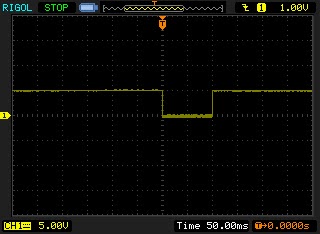
Moreover, if we scope on the PIN3,4,7,8,9,10 we may notice that as the datasheet said, the signal is active low when a coin is inserted on the specific line.
Because those PIN also inhibit a signal line we can even instruct the coin acceptor to disable a specific coin line. This will not be the case we are investigating here, I'm only interested in getting the coin signal.
For this reason I just connect the output of the Coin signal line, with a pullup resistor to our microcontroller.
That's easy, now it's just a pin reading matter, with a bit of debounching.
The schematics itself is simple. The main microcontroller is an ATmega8. The UART to USB adapter chip is the Silab CP2102, attached to a microUsb port.
For this project I've also design the PCB, which i prototype using a chinese PCBA service. We are able to build the final board after 3 prototype, that's because I'm not a pro in the PCB design, but I've to start somewhere. Then the company I work request 100 boards production from the chinese company. It was the first time that I try the PCBA service of a company, think this was a good experience, to start with a small and simple board like this one.
A three-phase brushless motor it is usually drive by six-state commutation step sequence.
The commutation sequence drive the motor coils in order to make it spin.
The picture above represent a standard commutation scheme, each line is the motor coil status.
Given a 360 degree commution space, each commuation happens takes a 60 degree space.
A coil it is usually driven by mosfet bridge.
The coil can be drive on or off, but we can also drive it in PWM.
The PWM scheme is the way the power gates bridge is controlled in order to drive each motor coil.
Brushless electric motor (BLDC motors) are synchronous motors that are powered by a DC electric source via an integrated inverter/switching power supply, which produces an AC electric signal to drive the motor. Hall sensored motors uses hall effect sensors or a rotary encoder to directly measure the rotor's position.
For an introduction to BLDC motors, you can take look at my sensored motor driver post, here: http://davidegironi.blogspot.it/2013/09/a-simple-brushless-sensored-motor.html
This library implements a brushless sensorled motor dirver for AVR ATmega.
This is exacly the same library as the previous linked, so, for further information on this library please look at the link above.
There are just a few difference due to the hall sensor presence. The motor position this time it is discovered using hall sensors insted of using the the ZC crossing detection.
When we get the hall sensor status, we can select the next hall sensor status we expect after the step emission. The hall sensor status expected to current status is defined in the bldc.h file.
The picture below reports the commutation step agains the next status expected.
Once again, this is a simple implementation of a sensored driver, there are improvements that can be made to make this driver works even better. The purpose of this implementation is to offer a simple yet hackable way to run a bldc sensored motor.
Code
find the source code for this project on the sensorless post linked above
Brushless electric motor (BLDC motors) are synchronous motors that are powered by a DC electric source via an integrated inverter/switching power supply, which produces an AC electric signal to drive the motor.
For an introduction to BLDC motors, you can take look at my sensored motor driver post, here: http://davidegironi.blogspot.it/2013/09/a-simple-brushless-sensored-motor.html or you can browse the internet, you will find there is a lot of litterature about BLDC motors.
This library implements a brushless sensorless motor dirver for AVR ATmega.
To write this library I take inspiration from the library above:
The code i propose is written, tested and compiled using avrgcc over an ATmega8 running at 16Mhz.
I've also tested a version of this code on ATmega8 running at 8Mhz. The aim of is project is to build a fairly simple bldc driver one can embed and easly modify in order to meet their own needs.
There are of course driver that performs better than this one, so if you are looking for best performance and you are using an ATmega micro, i suggest you to take a look at the SimonK firmware (https://github.com/sim-/tgy) or the BLHeli firmware (https://github.com/bitdump/BLHeli).
My previos driver you can find on links above does not fully implements PWM, also the brushless sensorless version to detect Zero Crossing reads the ADC voltage insted of using the internal ADC comparer.
Like the previos driver, this one implements a speed and direction (clockwise and anti-clockwise) controller.
Speed and direction can be set using the proper function, the speed have to be set using a 0 to 100 interval. 0 will stop the motor, direction has defined macro available for CW and CCW set.
In the sample main file the speed is driven by an RC input library, binded to the external interrupt input PIN.
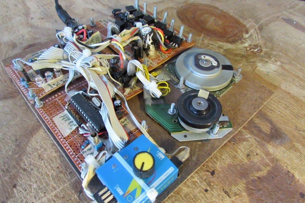
For the test project the RC signal generator is a servo tester.
The RC reader library can be found here: http://davidegironi.blogspot.com/2018/03/an-avr-atmega-rc-control-signal-reader.html
Settings for this library can be changed on the rcin2.h file.
The bldcsetup.h file containst the main settings. As example there you can find the RC input library enabler.
This driver implements 4 PWM schemes:
H PWM L ON: PWM is performed on the ON channel
H ON L PWW: PWM is performed on the OFF channel
H PWM ON: PWM is performed on UWV channels every 60degrees, starting from U ON-ON
H ON PWM: PWM is performed on UWV channels every 60degrees, starting from V OFF-NULL
The PWM scheme is the way the power gates bridge is controlled in order to drive the motor.
One can chose the PWM scheme in the bldcsetup.h file.
The main.c file is a sample running project that use this library to run a motor.
bldcsetupmicro.h file contains specific microcontroller definition, this file should allow the implementation of this library over others than the ATmega8 microcontroller. It contains ADC registry settings and TIMER settings.
This driver can run on many board pinout, input/output PIN can be changed in the bldcsetupboard.h file.
The adc mux schema represent the order of PIN chosen as Zero Crossing detection depending on the running step.
The commutation sequence is defined in the bldc.h file.
By default it is set as follow (first group is the U bridge switch, second is the V, third is the W):
Step 1: 10-01-00
Step 2: 10-00-01
Step 3: 00-10-01
Step 4: 01-10-00
Step 5: 01-00-10
Step 6: 00-01-10
The picture below represent the commutations:
The interface with the user consists in a bounch of function that performs:
initialization of the library
speed selection or retrive
direction selection or retrive
speed retrive in RPM
debug function to retrive the status of the driver
Two TIMER are implemented:
TIMER PWM: works as the PWM emitter, it emit the commutation to the power bridge according to the selected step
TIMER MAIN: select the step to emit, depending on speed and direction selection. It works in three modes:
startup mode: perform the startup sequence of step
emission mode: select the commution step to run and switch to non emission mode
non emission mode: check the BEMF for Zero Crossing detection, once the ZC is detected, the mission mode is triggered
Two error detection strategies are implemented, both the strategies can be enabled or disabled at compile time. ZC detection error and Max Ticks between steps detection. Both the strategies trigger a motor startup when the max number of errors is reached. The ZC detection errors makes a +1 increment whenever a ZC crossing should be detected but it was not. The Max Ticks between steps makes a +1 increment whenever a step happens.
The RPM speed estimation is performed assuming the TIMER A runs at a fixed frequency.
Further improvement can be made on the whole driver, expecially the startup stage.
WiiPoser is Wii Nunchuck + led matrix + pan/tilt servo laser pointer frame.
I've build this frame to test the Wii Nunchuck library years ago.
Nunchuck is a wii 2-axis joystick, two buttons and a 3 axis 2g accelerometer.
You can find the nunchuck driver here: http://davidegironi.blogspot.com/2012/11/avr-atmega-wii-nunchuck-library-01.html
This is just an unsuefull frame built to test some libraries.
Behind the canvas of the frame there's a 5x5 led matrix driven through a bunch of general purpose NPN transistors.
The main controller it's an ATmega8, running @8Mhz.
There's a pan/tilt servo bracket that moves the laser pointer.
The Wii Nunchuck drives the servos pointer.
One of the Nunchuck button change the led view mode, in mode one just one led is on, in mode two just one led is off.
The second button of the Nunchuck switch the laser pointer on and off.
The Nunchuck joystick is used to select which led has to be powered on or off.
If no movment is perceived the frame goes in a demo mode, the demo mode moves the servos and switch on and off the leds in a random mode.
A digital-to-analog converter (DAC) is a system that converts a digital signal into an analog signal.
The MCP4901, MCP4902, MCP4911, MCP4912, MCP4921, MCP4922 are DAC converters by Microchip.
They have 1 or 2 channel output, 8, 10 or 12 bit buffered voltage output.
The interface used to drive those IC is the SPI.
Driving that IC is pretty simple, expecially if you have a dedicated SPI hardware interface, like many microchip has.
The ATmega8, used in this example has a dedicated SPI Control Register (SPSR) that one can use to setup the SPI interface.
This library can drive more then one MCP49XX of the same series at the same time, this is done just by selecting the chip using a SS channel for each one.
A few functions are available in order to set a raw value for the DAC channel, a selected voltage, to power the IC down or up, and to get the actual raw value.
On compile time you have to set ports to use, and the MCP49XX family.
The sample schematics contains also an output stage build up using a LM358 opamp with a non-inverting configuration.
In non-inverting configuration the Gain is R2/R1 + 1, given R2 the resistor between out and - input, and R1 the resistor beteen - input and GND. The sample gain of 3.2 amplifiy the input signal taken from the DAC by 3.2, of course the output voltage can not exceed the power supply voltage of the opamp. For this reason if you supply the LM358 with a 12V supply, a sample output voltage of 2.4V will became 7.68V output.
The output current is limited to 20mA for a sink load and 40mA for a source load.
By simply adding a power MOSFET you can amply the output current that can be draw.
The example is provided runs a sine wave output or a selected voltage output.
All the setup parameters are included in the mcp49xx.h file.
The library proposed here can be ported to other microcontroller without difficulties.
This library was developed on Eclipse, built with avr-gcc on Atmega8 @ 8MHz.