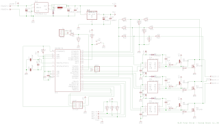
This board is the PCB version of the development board I've used to build the BLDC driver implemented here:
http://davidegironi.blogspot.com/2019/12/an-atmega-brushless-sensorless-motor.html
http://davidegironi.blogspot.com/2020/01/an-atmega-brushless-sensored-motor.html
The board max input voltage is 45V, that is the maximum supply voltage of step-down voltage regulator LM2596-12V.
This step-down regulator provides the power voltage for the IR2101 high and low side attached to the main power mosfets of the bridge motor driver. In this design i use IRF640 mosfets, but one can also use other kind of mosfets.
A 5V regulator provides the supply voltage of the main microcontroller.
The board works both for sensored and sensorless motors.
For sensorless motor EMF signal is catched by the voltage divider network attached to pin PD6, PC0, PC1 and PC2. The PD6 pin is used in the voltage comparer configuration.
For sensorled motors digital hall sensor inputs are read by the PB0, PB1 abd PB2 pins.
A 16Mhz crystal is attached to the main ATmega8 micro, even if I've tested this board and the driver at 8Mhz using the internal ATmega oscillator circuit.
A direction switch is used to select the spinning direction of the motor.
The UART RXD and TXD pins can be used for debug or driving purpose, as example one can easly implement a protocol that control the motor driver.
Least but not last, the RC Input pin can be used to read the input of a RC servo signal.
Schematics and Board - EagleCad
Notes
Notes
- read risk disclaimer
- excuse my bad english


