
The NRI G-13.mft by Crane (https://www.cranepi.com/) is a versatile and high secure coin validator.
It can be programmed using the propretary WinEMP software and PC interface, or event it has some DIP Switch that can be used to program the device.
Unluckily it does not come with a UART interface. But it features a "machine tester" I/O interface we can use to track the inserted coins.

On page 50/51 of the Technical Documentation for NRI G-13.mft G-13.mft parallel Standard, Casino and AMU Models (from Version /4) 05.05 Hns/WP/ds Edition 1.2 BA.G13MFTPAR4-GB, we find the specification for the interface we could use.


For the G-13.mft standard/Casino model – vending machine 10pin interface, we notice that
PIN 1 is the GND while PIN 2 the VCC, we can use those pin to power the device on.
Moreover, if we scope on the PIN3,4,7,8,9,10 we may notice that as the datasheet said, the signal is active low when a coin is inserted on the specific line.
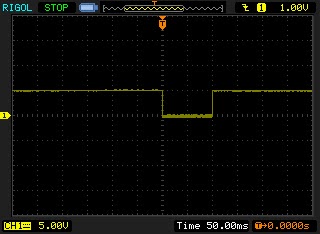
Because those PIN also inhibit a signal line we can even instruct the coin acceptor to disable a specific coin line. This will not be the case we are investigating here, I'm only interested in getting the coin signal.
For this reason I just connect the output of the Coin signal line, with a pullup resistor to our microcontroller.
That's easy, now it's just a pin reading matter, with a bit of debounching.

The schematics itself is simple. The main microcontroller is an ATmega8. The UART to USB adapter chip is the Silab CP2102, attached to a microUsb port.

For this project I've also design the PCB, which i prototype using a chinese PCBA service. We are able to build the final board after 3 prototype, that's because I'm not a pro in the PCB design, but I've to start somewhere. Then the company I work request 100 boards production from the chinese company. It was the first time that I try the PCBA service of a company, think this was a good experience, to start with a small and simple board like this one.

Code, Schematics and PCB
Notes
- read risk disclaimer
- excuse my bad english
Hi David! I'm very much looking for something sort of what you did. Can I find such a card? Maybe you have? (I need 20 of these very much!).
ReplyDeleteYou did a great thing !.
Successfully!
Hello, I don't have. I've build 100 of those cards, but all are gone now. You can ask for a PCBA service online, all the things you need are in the file above in this post.
DeleteHi! With this PCB you can not prevent the user to insert a coin before you are ready for it?
ReplyDeleteI also do not understand, is this standard CP2102? Because you have another PIN near Pin1
DeleteHello Michael. This is a standard CP2102. This board do not disable the coin acceptor. In order to do this you have to populate some other pins and output a logic signal over that pins. I forget what pins are, but you can find in the manual of the coin acceptor. If I remember well it's all written there. We don't need this behavior so I don't implement this. Of course you also have to update a little bit the code for the ATmega in order to drive the populated output pins. It will not be so difficult.
DeleteThank you for the answer!
DeleteI looked as you say in the documentation of the coin acceptor verifier. and there it appears that pin 2 is used to delay the receipt of INHIBIT coins. and you have this pin in use for to connect it to Pin 1 of the ATmega
Sorry I was wrong. Pin No. 2 of the G-13, you connect it to Pin No. *9* of ATMega. (Pin No. 2 Use - BY Documentation Page 62 - For Delay of coins when you do not want)
DeleteYou are welcome.
Delete